 OTHER
THINGS
OTHER
THINGS OTHER
THINGS
OTHER
THINGS
![]()
Fig. 1 Schematic of a Thermal Pump
Extensive numerical and experimental studies on thermal pumping have been carried out and they show good agreement with the earlier developed theory. Heat transfer enhancements up to five orders of magnitude in excess to that possible in the absence of axial fluid oscillations have been found under appropriately tuned conditions depending on capillary diameter and oscillation frequency. Numerical calculations have also been made of the time-dependent fluid motions in the end chambers of the thermal pump. A counterrotating vortex pair is observed to be present in the end chambers throughout the oscillation cycle and definite fluid jets entering into the end chambers from the connecting pipes are observed. In Figure 2 we show a typical temperature profile of the fluid within a simple 2D thermal pump model at one point within the oscillation cycle, for the case of a very short single connecting channel. Note the thermal plume structure with blue representing cold and red hot fluid.
Fig. 2 Temperature Plumes Produced in a Thermal Pump Model
The calculation leading to this figure where obtained by Dr. Guo (PhD ,University of Florida,1996) using a time periodic extension of the SIMPLE technique. Some recent work by H.Akachi(Actronics,Tokjo) and F.Polasek(Inst.Machine Design,Prague) have made use of this thermal pumping process in the design of a new type of heat pipe in which an axial temperature gradient produces two-phase fluid oscillations, thus eliminating the need for pistons in the end chambers.
![]()
2) ENHANCED DIFFUSION AND
SEPARATION
OF SPECIES IN FLUIDS:
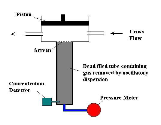
Investigations in this area have been mainly concerned with experimental measurements of enhanced axial dispersion in gases and liquids in open-ended capillaries when an axial concentration gradient exists and the fluid is oscillated axially. This work, which has been carried out in collaboration with Dr. Marc Jaeger of the Physiology Departmant at the University of Florida, has shown that it is possible to increase the axial dispersion of species in fluids by orders of magnitude and to produce very effective species separations without the need for semi-permeable membranes. The separation becomes especially large under tuned conditions where the half period of the fluid axial oscillations just equals the time it takes for a molecule to diffuse from the capillary axis to the tube wall. For typical oscillation frequencies in gases of about 10 Hz, tuned conditions correspond to capillaries of approximately 2mm diameter. Also, it has been found that separation of gas species becomes especially dramatic when a counterflow is introduced under tuned conditions. Most recently these dispersion studies have been extended to an examination of gas washout from closed end containers containing beads. Result have been very encouraging, indicating that gases trapped in dead-end spaces can be rapidly removed by applying pressure oscillations at the open end. A schematic of the washout apparatus being used is shown in Fig.3.
Fig.3-Apparatus for Measuring Gas Washout Times
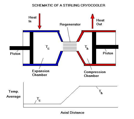
Fig. 4 Stirling Refrigerator Model
In this model, the open-ended connecting channels act as regenerators since they are of sufficiently small cross section (channel half width a=0.1 cm in the present study) so that the gas temperature will adjust itself to the wall temperature in its path through them. If one now imposes a low wall temperature along the left chamber walls and a higher temperature along the right chamber walls, the gas( helium at either 1 or 10 atmosphere mean pressure) is compressed mainly when the bulk of the gas is in the hot chamber and is cooled by expansion when the gas is mainly in the cold chamber. One thus has essentially a cryocooler in which heat is extracted from the cold chamber walls and expelled through the hot chamber walls. A good indication of this behavior is shown in Figure 5.
Fig. 5 Temperature Within the Stirling Refrigerator Model at Two Points in the Oscillation Cycle
We have been able to achieve a low temperature of about 200K when the hot side of this Stirling configuration is maintained at 300K and a cooling rate of about 1 watt/cm^2 of regenerator cross-section is maintained. Application of such a device for the cooling of certain infrared radiation detectors is clear. The calculations needed to produce Fig.5 where carried out at the Pittsburgh Supercomputing Center. A pulse tube, which has a much lower efficiency than a Stirling cryocooler, has the advantage that there are no moving parts in the low temperature chamber. It can be simulated with the above 2D model by holding the left piston stationary.
![]()
4) THERMAL PULSE PROPAGATION IN PIPES OF FINITE WALL CONDUCTIVITY:
Another study in which we have been involved
deals
with the propagation of a heat pulse superimposed on a
steadily flowing
fluid in a tube whose wall has finite thickness and finite
thermal
conductivity.
A general theory for this process , based on a multiple time
scale
expansion,
has been developed ( Int.J. Heat and Mass Transfer
40,391-1400,
1997 ). It is found that the thermal pulse generally
propagates slower
down the tube than the mean fluid speed. This is very
reminiscent of
what
occurs in chromatograpy and may find application in an
accurate
determination
of material heat capacity and in volume flow rate
determination. In
Fig.
6 we show the temporal behavior for one of these thermal
pulses at two
points along the tube.
Fig.
6 Thermal Pulse as a Function of Time at Two Points Along a
Pipe
The initial heat input is here in the form of a rectangular temperature pulse. One sees essentially a dispersing Gaussian structure propagating at a unique sub-average flow velocity. Experiments have recently been run by Dr. Jaeger using water flowing in a 3.3mm ID copper pipe having a wall thickness of 0.7mm. At a Peclet number of 43, the peak of the thermal pulse is observed to move at about 0.54 of the mean flow speed and takes about 14 minutes to reach an observation point 200 cm from the initial heat application point. This result is found to be in excellent agreement with theoretical predictions.
![]()
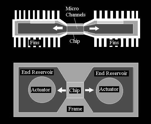
5) INJECTION COOLING OF PARALLEL PLATE ARRAYS:
In our latest studies we have been examining
the
cooling
of an array of self-heating parallel plates by periodically
injecting
and
removing a cooling fluid into the micro-channel array formed
between
this
set of plates. For certain applications such as the cooling of
electronic
microchips, this procedure might offer advantages over
standard
convection
loop cooling, especially when going to smaller
dimensions where
the
spacing between individual plates becomes the order of 100
microns. In
Fig.7 we give the side and top view of a possible
injection
cooling
configuration having an
Fig.7-Side and Top View of a the Fluid Injection Device for Heat Spreading
overall dimension of about 3x2x2cm3.
The
heat removal rate is found to become especially effective when
the
residence
time of the injected cold fluid is just long enough to heat it
to
within
about 10% of the plate temperature and then quickly remove it
to be
replaced
by a new batch of colder fluid from the second end chamber.
Some
calculations
carried our by one of our students(Whitney Jones, MS Thesis,
University
of Florida 1999) using a Laplace transform approach in
conjunction with
an asymptotic evaluation of the resultant Bromwhich integral,
shows
that
the heating of the plates(when thought of as a fin array
attached to a
1cm2 chip generating 200 watts), can be kept well
below the
typical 85degC upper limit allowed for electronic
microcircuits . In
the
calculations it was assumed that the microchannels
between the
plate
array were each 200 microns wide, that the total plate area
was 30cm2,
that the injection fluid was water at room temperature, and
that the
injection
frequency was 10 Hz.. The
reason for the effectiveness of this cooling
process
is clearly the very thin thermal boundary layers existing
there.
![]()
Return to the MAE
DEPARTMENTAL PAGE
Return
to
HOME PAGE
Others of our WEB pages include-
http://www.mae.ufl.edu/~uhk/MATHFUNC.htm
http://www.mae.ufl.edu/~uhk/ANALYSIS.html
http://www.mae.ufl.edu/~uhk/DYNAMICS.html
![]()