This webpage
outlines the knowledge necessary to safely program, set up, and run the CNC
lathe in the Design & Manufacturing Laboratory. Many of the images
and links are authored by others and hyperlinked accordingly.
Table of Contents
7.
Tool Loading
8.
Work Holding
10. Program
Graphics / Simulation
11. Program
Dry (aka Test) Run
12. Prototype
(First Part) Run
13. Production
Run
14. Cleanup
15. Important
Points
16. Bonus
Stuff
17.
Machine Manuals & Reference Documentation
Part CAD Model & Drawing [RETURN TO
T.O.C.]
Always begin
with an accurate CAD model of the part to be made. Once the part
model is checked for accuracy, a good quality drawing must be made of
the part that includes appropriate tolerances for each part feature, as
well as notes about which surfaces need finishing, how good the
finishes must be, and allowable (i.e. maximum) fillet sizes on each part
feature. A printed copy of this drawing will be used both for part
programming and post-machining inspection, so take the necessary time to
make an accurate and easily readable drawing. If you can’t do this,
you don’t have the skills, patience, or time to attempt part manufacturing.
The part
drawing and dimension datums should be displayed in accurate relation to the
machine’s axes to decrease the risk of miscommunication between part
orientation once in the machine and the coordinates displayed on the machine’s
readout. In the drawing below, for
example, notice how the Z-axis of the part is horizontal and the Z-zero is on the
tailstock side of the part / drawings, exactly as it would be when cutting it
in the machine.
For most
parts manufactured on the DML CNC lathe, the toolpaths are programmed manually,
because the slightest misunderstanding of the code generated using CAM software
can be catastrophic to the user, machine, and/or cutting tool. When
creating a part drawing used to program the CNC lathe, all part diameters must
be dimensioned, as well as the starting and ending coordinates for all
arcs/radii. All Z-axis coordinates should be dimensioned from the face of
the part as shown in the sample part drawing below.
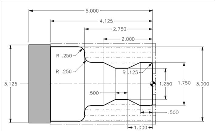
Sample CNC
lathe part drawing (note starting and ending coordinates for arcs are missing)
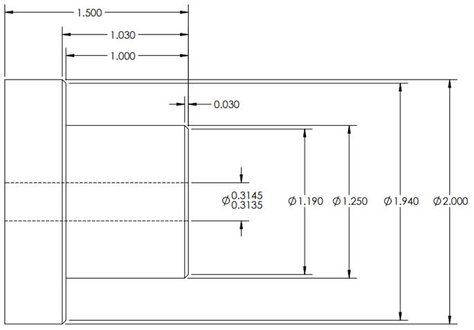
Part Setup Sheet [RETURN TO
T.O.C.]
In addition
to an accurate and clear detail drawing, you must also complete a setup sheet
for the machine you plan to use to manufacture your part:
The setup
sheet includes details of each tool used in the manufacturing, as well as
sketches and notes explaining where your part datums/zeros are located for each
operation. Worded another way, the setup sheet should contain ALL
information necessary for another competent operator to successfully setup and
run your part program.
The part
setup sheet should take into account the number of tools required for the
particular part geometry and material being machined, as well as the number of parts
(i.e. more parts in tougher materials require separate roughing and finishing
tools if holding tight tolerances and surface finish requirements). Particular part geometries may require more
than one tool to accurately complete a curvature or the desired end geometry. These discrepancies should be clearly accounted
for and explained on the part set up sheet. This document must be both detailed and
accurate to ensure a properly machined part.
In summary,
poorly completed setup sheets result in poorly completed parts.
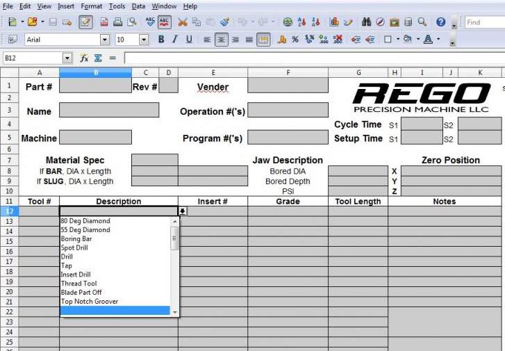
Setup sheet
details for CNC lathe
Here are
a few interesting comments about The Art of the Setup Sheet
Part Programming Methods [RETURN TO
T.O.C.]
There are
three ways to program CNC machines: CAM (computer aided manufacturing),
conversational (subroutine library), or manually hand writing G&M (geometry
and miscellaneous) code. As mentioned previously, we primarily use manual
hand coding for programming the DML CNC lathe because the slightest
misunderstanding of the code generated using CAM software can be catastrophic
to the user, machine, and cutting tool.

Example of
simple CNC lathe program
Most parts
comprised of lines and constant-radius arcs are easily programmed by hand and
cut on the CNC lathe. For more complex
part geometries (i.e. a nose-cone containing complex ellipsoid geometry), the
part model is directly imported into the CAM software, which in turn is used to
generate the toolpaths used to cut the part.
Hand Coding Programming [RETURN TO
T.O.C.]
This section explains safe programming
practices for the Haas SL-10 CNC lathe. A lab
wheel hub example program will be used to demonstrate the following
operations found on the noted pages of the SL-10
Operator’s Manual:
|
G00 Rapid Motion Positioning
(P.118) G01 Facing Operation (p.118) G01 Automatic Chamfering
Option (p.121) G40 / G41 / G42 Tool Nose
Radius Compensation (p.130) G50 SXXXX Spindle Speed Clamp
(p.130) G71 OD/ID Stock Removal Cycle
(p.133) G75 OD/ID Grooving / Parting
Cycle (p.147) G83 Normal Peck Drill Canned
Cycle (p.155) G86 Bore and Stop Canned
(Reaming) Cycle (p.156) G96 / G97 Spindle Speed Modes
(p.162) |
|
1.
General Program Format
a. Handwrite code in a text editor such as
Notepad
b. A percent (%)
sign must appear as the first and last line of every program
c. The second line of code should follow the
format: O##### (Name of Program)
d. At the beginning of each operation and next
to each tool change, leave a comment in parentheses stating what the operation
is:
i.
For example (DRILLING OP) or T303
(0.5″ Jobber Drill)
ii. The machine ignores any comments in
parentheses, but comments cannot be greater than 80 characters and cannot
contain additional parenthesis inside parentheses
e. Before the last percent sign at the end of
the program, specify an M30 which denotes
program end
f. All coordinate values should be written with
a decimal place
i. G00 X3 will be interpreted as “rapid to an X-axis
position that is a distance of 0.0003” from spindle centerline”
ii.
G00 X3.0 will be interpreted as “rapid to an X-axis
position that is a distance of 3.0” from spindle centerline”
iii.
CAUTION: MAKING THIS ERROR CAN CAUSE A
COLLISION. ALWAYS PROOFREAD YOUR CODE, RUN A SIMULATION, AND DO A DRY RUN
AT 5% RAPID EVERYTIME ANY CHANGE IS MADE TO A PROGRAM, NO MATTER HOW SMALL THE
CHANGE MAY BE.
2.
Safety Block
a. The safety block should exist at the start of
every program, and is typically on the third line:
G00 G28 G40 G54 G80 G97
G00 – Rapid Motion Positioning Mode
G28 – Return To Machine
Zero (Home) Positon
G40 – Tool Nose Compensation Cancel
G54 – Select Work Coordinate System
G80 – Canned Cycle Cancel
G97 – Constant Surface Speed OFF (i.e. Constant
Spindle Speed mode)
3.
Tool Changes
a. Always return home for tool changes, specifying
a move in the X-axis away from your part, then specify
a z-axis move to home the tool
i. G00 G53 X0.0
ii.
G00 G53 Z0.0
iii.
CAUTION: Specifying G28 X0.0 Z0.0 will command the machine to send
the tool to the X0.0 and Z0.0 of the current work (part) coordinate system as a
vector move AND THEN HOME, causing the
tool to CRASH into the part
b. Do not program vector rapid movements (moving
the X and Z axes at the same time)
i. The code is executed line by line, so placing
an X and Z coordinate in the same line will simultaneously move both the X and
Z axes to each coordinate (i.e. G00 X0. Z0.)
ii. CAUTION: Specifying G28 will command the machine to send
the turret home using a rapid vector move, so use G53s instead, as described
above
iii.
CAUTION: MAKING THIS ERROR CAN CAUSE A
COLLISION. ALWAYS PROOFREAD YOUR CODE, RUN A SIMULATION, AND DO A
DRY RUN AT 5% RAPID EVERYTIME ANY CHANGE IS MADE TO A PROGRAM, NO
MATTER HOW SMALL THE CHANGE MAY BE.
4.
Facing
Operation: G01 (p.118)
The line (N) numbers in the
following program are optional and are included to improve clarity in the
subsequent explanations.
|
N1 (FACING OP) N2 G28 (Home
turret) N3 T0101 (CNMG
432) N4 G00 G54 Z0. N5 G00 X2.1 N6 G50 S1500 N7 G96 S400 M03 N8 M08 N9 G01 X-0.062
F0.005 N10 G00 Z0.1 N11 G00 X2.1 N12 M09 N13 M05 N14 G00 G53 X0. N15 G00 G53 Z0. |
|
N1 (Facing Op) – Begin with a comment in parentheses describing the operation
N2 G28 (Home turret) – Always send the turret to its HOME location (G28) before
executing a tool change
i. On the Haas CNC lathe, G28 will home the
X-axis first, and then the Z-axis when running a program
ii. CAUTION: NEVER program G28 X0. Z0., as
doing so invokes a different mode that will send to the tool to part location
0,0 and THEN send it home, causing the tool to CRASH into the part
N3 T0101 (CNMG 432) – Select the turning facing tool by calling for a tool change
i. Tool change commands follow the format TXXYY,
where XX is the turret tool number, and YY is the tool offset to
be used for tool XX
ii. In the same line as the tool change command,
include a description of the tool in parentheses: (CNMG
432)
iii.
CAUTION: a TXXYY command IMMEDIATELY
executes a tool change AT THE CURRENT TOOL/TURRET LOCATION!
N4 G00 G54 Z0.0 – Rapidly move (G00) the turning / facing tool to the G54 work
offset Z0.0 part location
N5 G00 X2.1 – Rapidly move to an X position at least 0.050” radially from the
outside diameter of the work stock; since G00 is modal, it is optional on this
line
N6 G50 S1500 – Limit (clamp) maximum spindle speed to 1500 RPM since the part
is being held in a 6” chuck due to the higher inertia and reduced clamping
force of a traditional 3 jaw chuck at higher speeds
N7 G96 S400 M03 – Turn Constant Surface Speed ON (G96) at 400 SFM and turn
the spindle ON in the forward or clockwise direction (M03)
i. CAUTION:
When facing with a constant surface speed (G96) the spindle speed will try to
increase to maximum machine speed (6000 RPM) as the tool approaches part
centerline. This is VERY unsafe for all but the most experienced
operators using collet chucks with short workpieces, and why the speed MUST be
limited to a safe maximum value by programming a G50 prior to commanding a
G96. This maximum value is dependent on your workholding and clamping
force. Start small and work your way up, but generally do not exceed
2,000 RPM.
N8 M08 – Turn coolant ON
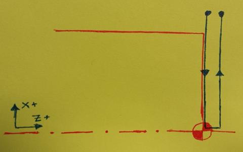
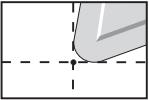
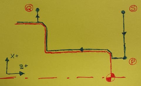
N9 G01 X-0.062 F0.005 – Feed the tool to part centerline at a controlled 0.005 in/rev
i. G01 – Linear Interpolation Motion vs G00 –
Rapid Motion
ii. X-0.062 – The tool must feed across the
center line of the part by a distance greater than the length of the tool nose
radius in order to completely face the part. The graphic below illustrates
where the machine thinks the point of the tool exists. In this example we are
using a CNMG 432 insert that has a tool nose radius of 2/64”
(0.03125”), so we travel to X-0.062 (on the diameter) to completely face the
part.
iii.
F0.005 – The default units for
feedrate are inches per revolution
N10 G00 Z0.1 – Rapidly (G00) move the tool AWAY from the
finished surfaced
N11 G00 X2.1 – Rapidly (G00) move the tool to a safe
location OUTSIDE the part stock diameter; since G00 is modal, it is optional on
this line
N12 M09 – Turn coolant off (M09)
N13 M05 – Stop the spindle (M05)
N14 G00 G53 X0. – First send the machine home in the
X-direction; since G00 is modal, it is optional on this line
N15 G00 G53 Z0. – Then send the machine home in the
Z-direction; since G00 is modal, it is optional on this line
5.
Turning Operation: G71 O.D./I.D. Stock
Removal Cycle (p.133)
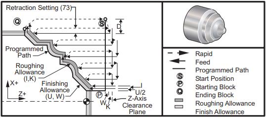
a. Cycle Parameters:
*D: Depth of cut for each pass of stock removal, positive
*F: Feed rate to use throughout G71 PQ
block
*I: X-axis size and direction of G71
rough pass allowance, radius
*K: Z-axis size and direction of G71
rough pass allowance
P: Starting
Block number of path to rough
Q: Ending
Block number of path to rough
*S: Spindle speed to use throughout
G71 PQ block
*T: Tool and offset to use throughout
G71 PQ block
*U: X-axis size and direction of G71
finish allowance, diameter
*W: Z-axis size and direction of G71
finish allowance
*indicates
optional
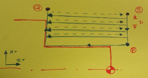
b. Type I G71
i. Specified by only an X or Z
move in the block number specified by P, and does not allow the X axis tool
path to reverse during a cut (as illustrated in the G71 graphic above)
ii. Example: N100
G01 X2.1
c. Type II G71
i. Specified by both an X and Z
move in the block number specified by P, and allows the X axis path to reverse
direction during a cut, as illustrated in the graphic below
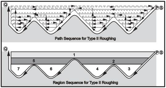
ii. Example: N100
G01 X2.1 Z0.05
iii.
TIP: It’s good
practice to define EVERY G71 toolpath as a Type II, regardless of whether it is
actually is or not.
d. Finishing Allowance
i. As shown in the illustration above, optional
U & W parameters allow the G71 canned cycle to leave material on the
surface for part measurement and compensation or for another tool to perform a
finish cut after the G71 is used to complete the roughing
ii. These values can also be used to adjust the
final feature size if the same tool is used for roughing and finishing (as is
often the case for low qty. runs or when working in easy-to-machine materials
like aluminum
e. Roughing Allowance
i. As shown in the illustration above, optional
I & K parameters allow the G71 canned cycle to leave material on the surface,
BEYOND ANY SPECIFIED FINISHING ALLOWANCE
ii. Since the G71 cycle leaves a staircase
profile on any PQ cycle that has combined X and Z motion, specifying roughing
allowance is essentially a semi-finishing pass, meaning it removes the
staircase and leaves the finished surface offset by the value specified via any
finishing allowance parameters
f. Example #1: G71 (Type II, No Chamfers)
|
N20 (TURNING OP) N30 G28 (Home turret) N40 T101 (CNMG 432) N50 G00 G54 Z0.1 N60 G00 X2.1 N70 G50 S1500 N80 G96 S400 M03 N90 M08 N100 G71 P200 Q250 D0.050
I0.005 K0.005 N200 G00 X1.25 Z0.1 N210 G01 Z-1.0 N250 G01 X2.1 G00 G53 X0. G00 G53 Z0. |
|
N100 G71 P100 Q200 D0.050 I0.01
K0.005 – Cut shoulder profile using 0.050” radial
DOC, 0.01” roughing allowance, and 0.005” finishing allowance
g. Example #2: G71 (Type II, Chamfers + Tool
Nose Compensation (TNC))
|
N20 (TURNING OP) N30 G28 (Home
turret) N40 T101 (CNMG
432) N50 G00 G54 Z0.1 N60 G00 X2.1 N70 G50 S1500 N80 G96 S400 M03 N90 M08 N100 G71 P200
Q300 D0.050 I0.005 K0.005 N200 G00 G42 X1.2
Z0.1 N210 G01 Z0.0 N220 G01 X1.2
K-0.030 N230 G01 Z-1.0 N240 G01 X2.0
K-0.030 N250 G01 Z-1.5 N300 G00 G40 X2.1 G00 G53 X0. G00 G53 Z0. |
|
N200 G01 G42 X1.2 Z0.1 – Enable Right Hand TNC (Tool Nose Compensation) to account for
tool nose radius when performing combined XZ motions (p.130
in SL-10 Operator’s Manual)
N220 G01 X1.25 K-0.030 – Cut a .030” x 45° chamfer on corner of part using G01 corner
chamfering option (pp.119-121
in SL-10 Operator’s Manual)
N300 G00 G40 X2.1 – Cancel TNC (Tool Nose Compensation) at end of programmed tool
path (p.129
in SL-10 Operator’s Manual)
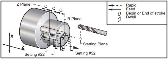
6.
Drilling Operation: G83 Normal Peck Drilling Canned Cycle (p.155)
a. Cycle Parameters:
F: Feed Rate
*I: size of first cutting depth
*J: amount to reduce cutting depth
each pass
*K: minimum depth of cut
*L: Number of repeats
*P: The dwell time at the bottom of
the hole
*Q: The cut-in value, always
incremental
R: Position of the R plane
*W: Z-axis incremental distance
*X: X-axis motion command
*Z: Position of bottom of hole
*indicates
optional
b. Drill Zero – the tip of the drill is zeroed
on the probe, so always account for the length of the taper when drilling
c. Example:
(DRILLING OP)
G28 (Home turret)
T303 (0.297” Drill)
G00 G54 Z0.1
G00 X0.0
G97 S1500 M03
M08
G83 Z-1.625 Q0.1 R0.2 F0.004
M09
M05
G53 G00 X0.0
G53 G00 Z0.0
G97 S1500 M03 – Turn Constant Spindle Speed ON (G97) at 1500 RPM and turn
the spindle ON in the forward or clockwise direction (M03)
G83 Z-1.625 Q0.1 R0.2 F0.004 – Drill 1.625” deep using 0.1” peck depths and 0.004”/rev feedrate
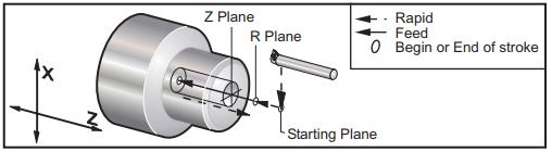
7.
Reaming Op: G86 Bore and Stop Canned Cycle (p.156)
a. Cycle Parameters:
F: Feed Rate
*L: Number of repeats
R: Position of the R plane
*U: X-axis incremental distance
*W: Z-axis incremental distance
*X: X-axis motion command
*Z: Position of bottom of hole
*indicates
optional
b. Example:
(REAMING OP)
G28 (Home turret)
T505 (0.376 Reamer)
G00 G54 Z0.1
G00 X0.0
G97 S750 M03
M08
G86 Z-1.5 F0.004 R0.2
M09
M05
G53 G00 X0.0
G53 G00 Z0.0
G86 Z-1.5 F0.004 R0.2 – Ream 1.5” deep using 0.1” peck depths and 0.004”/rev feedrate
stopping the spindle at the bottom of the hole and retracting
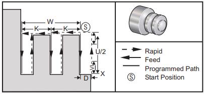
8.
Parting Example: G75 OD/ID Grooving Cycle (p.147)
a. Cycle Parameters:
*D: Tool clearance when returning to
starting plane, positive
*F: Feed rate
*I: X-axis size of increment between
pecks in a cycle (radius measure)
*K: Z-axis size of increment between peck
cycles
*U: X-axis incremental distance to
total pecking depth
W: Z-axis
incremental distance to furthest peck cycle, signed
*X: X-axis absolute location total
pecking depth, signed diameter
Z: Z-axis
absolute location to furthest peck cycle, signed
*indicates
optional
b. Example:
(PARTING OP)
G28 (Home turret)
T1111 (PART OFF, ZERO ON TSS)
G00 G54 Z-1.5
G00 X2.1
G50 S1000
G96 S400 M03
M08
G75 X0.375 I0.1 F0.002
G97 S500 M03
G01 X0.4 F0.02
G01 X0.0 F0.002
G01 X2.1 F0.02
M09
M05
G53 G00 X0.0
G53 G00 Z0.0
G75 X0.375 I0.2 F0.002 – Part-off workpiece to Ø0.375” using 0.1” radial pecks and
0.002”/rev feedrate
G97 S500 M03 – Turn spindle on at constant 500 RPM so part does not fly around
when it is parted off
G01 X0.4 F0.02 – Briskly move back into the previously cut groove
G01 X0.0 F0.002 – Complete the part-off at 0.002“/rev feedrate
G01
X2.1 F0.02
– Briskly move back to a safe
location outside the part diameter
Programming Tips [RETURN TO
T.O.C.]
1.
Calculate speeds
and feeds using the
information presented on the EML2322L Advanced Speeds and Feeds page.
If you don’t understand how your feeds and speeds
are calculated, DO NOT continue. “I
just used what someone else gave me” is NEVER an acceptable justification for
breaking a tool or yanking a part out of the chuck because you didn’t
understand what you were doing. The linked document is easy to understand
and after reading it thoroughly, you can ask Mike as many questions as you
like.
2.
Understand Ft
= Ks × a × fr, where
Ft is the tangential cutting force
Ks is the material cutting
stiffness
a is the
depth of cut
fr is the feed per revolution
Therefore cutting forces are linearly
proportional to depth of cut and feedrate, and aggressive programming
parameters on the lab’s small CNC lathe place larger moments on the cutting
tool (deflecting it in the turret and causing chatter) and workpiece (trying to
pull it out of the chuck or collet). So it’s better to use tooling that
allows for higher cutting speeds when trying to reduce
cycle time.
3.
Prioritize safety
over speed when programming prototypes. Never program a vector move when running a
prototype; always program the Z motion first and THEN the X motion so you can
tell if the offset is correct when the tool is moving into position relative to
the face of the part. This applies for all tools: turning, facing,
grooving, drills, reamers, taps, countersinks, etc.
4.
Be careful of TXXXX commands on
CNC lathes. Unlike most
CNC milling machines, a CNC turret lathe always has its tools ready to make a
tool change. For that reason, there is no default “safe tool change
location” for most CNC lathes; they will program a tool change wherever the
turret is located when a tool change (TXXXX, where XXXX is the tool number and
offset, for example T1010) is called. If you call a tool change while a
cutting tool is close to the spinning (or stopped) chuck, the CNC lathe has no
problem trying to run every tool on turret right through the chuck on the
machine while spinning 5,000 rpm.

5.
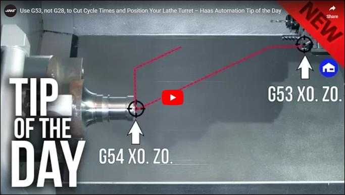
Be very careful of G28s on CNC
lathes. Depending on the run mode,
many CNC lathes perform a vector home move when executing a G28, so always
expect that. This can cause a serious crash when calling G28 with a tool
too close to the part or the live center. A safer way is to execute a G53
X0. command first, which moves the X axis to its fully
retracted position. And then executing a G53 Z0. command to move the Z axis to its fully retracted
position. Here is an
excellent video explaining the difference.
6.
Program reamers
properly. Reamers should be run at half
the spindle speed and twice the feedrate of the comparable size drill bit.
They should also be retracted with the spindle off to preserve the finish and
mitigate bell-mouthing of the hole entrance.
7.
Long tools do not
like high speeds.
Longer tools need their spindle speeds decreased by as much as 75% to reduce
vibration to prevent premature tool failure. A rule of thumb that
works well is to reduce the calculated spindle speed by 25% for every tool
diameter D over 2XD cutting depth and only increase your spindle speed after verifying
adequate cutting tool stiffness and chip evacuation.
Tool Selection [Printed
(Condensed) Version] [RETURN TO T.O.C.]
General
guidelines for selecting appropriate cutting tools when turning:
1.
Understand
selecting cutting tools for CNC turning is inherently more complex than
selecting cutting tools for CNC milling because milling basically uses two types of tools: endmills and
drills. Facemills, fillet tools, reamers, and
taps all fall into these two categories. But when it comes to CNC
turning, there is a myriad of different types of tools: facing, turning, profiling,
grooving (OD, face), parting, drilling, reaming,
threading, knurling, etcetera. On top of that, when selecting endmills
for CNC milling, there are only a few geometries to choose from: those for
milling weaker materials and those for milling stronger ones. The
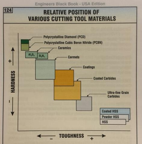
following images are taken from the Engineers Black Book, an
exceptional resource on the topic of cutting tool identification and selection.
2.
Understand
selecting cutting tools for CNC turning centers is a tradeoff between toughness
and hardness (i.e. wear resistance). Stated another
way, select the toughest tool that will last long enough do the job (which
coincidentally should also result in the cheapest cost per cutting edge). You already know HSS tools are much
tougher (resistant to impact without chipping) than WC. However, WC tools
are available in a spectrum of recipes that target applications requiring
higher toughness or higher wear resistance:
3.
Understand cutting
tougher, higher strength materials exceeds the limits of traditional (high
speed) steel based cutting tool materials. Clive summarizes it really well here.
Carbide started out as negative rake because the material is inherently more
brittle than any tool steel and positive rake cutting
produces forces tending to fracture the tip whilst negative rake geometries
directs the forces into the main body of the material. Hence negative
rake cutting tools are far more durable.
The flip side is that negative rake cutting
needs more power and tends to require better control of what's going on to give
a good finish. It was found that if a negative rake cutting tool were driven sufficiently hard
the power consumption per cubic inch of material removed decreases quite
significantly. The tool runs a lot hotter but carbide can take
it in compression. Operating in this region also generally gives a better
finish due to the high temperatures acting to plasticize
the metal along the shear line. Interestingly, if you get the operating
conditions right, most of the heat goes into the chip rather than the work
piece which stays relatively cool. It’s still hot though. Hence the
major thrust of carbide tool development was to exploit hard driven
tooling for rapid metal removal with good finish in industrial
situations. Generally finishing cuts are alien to negative rake tooling,
which is inherently poor at small cuts anyway, with work going direct to size
from decent cuts.
Positive rake tooling came along later as
material improvements led to stronger cutting edges. In general positive
rake tooling was developed to allow small depths of cut, particularly on
delicate components, whilst retaining carbide’s ability to cope with high
temperatures and fast metal removal. An industrial driver was the
potential cost reductions in changing from re-grinding tools to simple on
machine changing without needing to reset cutter holder position. For
this reason, a LOT of indexable tooling (steel or WC
toolholders with replacement WC inserts) is used on modern turning centers.
The latest developments are the super sharp inserts which rival diamond in
their ability to produce optical finish from fine cuts. Positive rake
tooling is still relatively delicate and easily chipped compared to HSS.
In particular care is needed when starting the cut.
Bottom line is that carbide of
any sort is not a straight substitute for HSS in any shape of form. For
proper utilization it needs speed and firm feeding. It’s important to remember
the material is strong in cut and at high temperatures but the inherent
brittleness remains so it is relatively easily damaged when entering the
cut. Carbide inserts are highly optimized for various duties, hence the
gazillion type numbers. Smaller lighter machines cannot properly utilize
them but there are types and grades which work well under such conditions,
usually very different to those they are designed for.
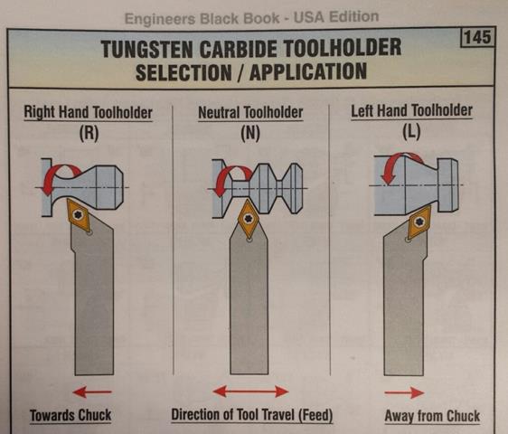
4.
Types of indexable toolholders. In general there are three types of indexable toolholders: right hand (R), neutral (N), and
left hand (L), depending on what side of the workpiece is being cut.
5a.
There is an alphabet soup of insert
types and shapes. No
literally, there really is.
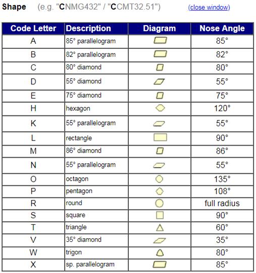
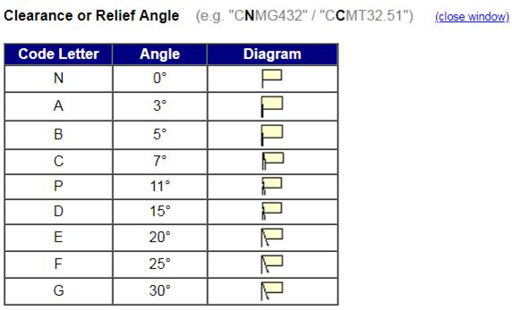
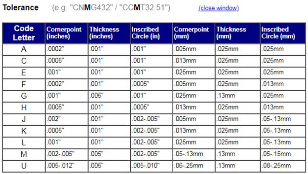
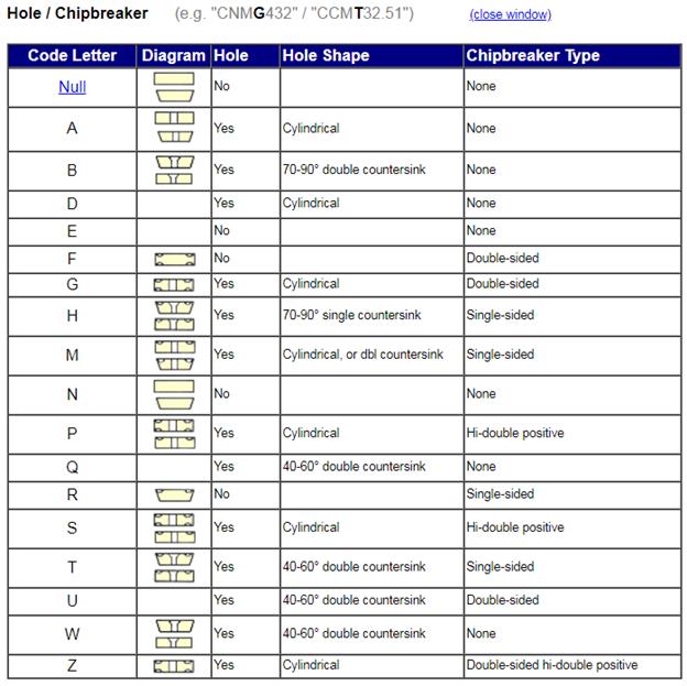
5b. When you add in the insert
clearance or relief angle, tolerance classification, hole / chipbreaker
geometry, size, thickness, wiper geometry information, and cutting edge preparation,
it’s enough to give anyone except a cutting tool nerd a headache. Really. Fortunately each cutting tool
manufacturer that isn’t a joke deciphers all of this information in their
cutting tool catalogs. The Engineers
Black Book is another GREAT reference for this info, as is the Carbide Depot’s Insert
Designation Chart (from which the following images are taken):
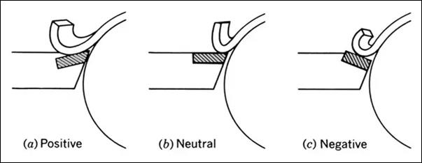
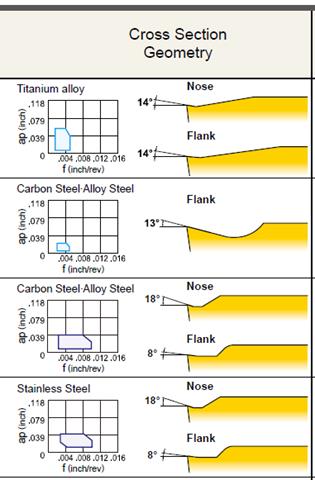
6a. Rake
angle (general definition). Rake
angle is the effective angle at which the cutting tool is presented to the
workpiece. There are three general categories of rake angle: positive, neutral,
and negative, as shown in the illustration below. Positive rake angles
are used for cutting weaker materials like aluminum and plastics. Neutral
rake angles are used for cutting stronger materials like low carbon and
normalized alloy steels. Negative rake angles are used for cutting the
strongest materials like heat treated steels. Stainless steels and
aerospace alloys such as titanium, Inconel, and the like are cut with positive
rake tooling with a honed top-edge land, versus a super-sharp ground top-edge
with essentially zero land width, as shown below.

6b. Rake angle (indexable,
neutral relief toolholders).
Because of the strengths of carbide inserts, indexable
toolholders which take neutral relief (not rake!) inserts,
are typically manufactured with negative rake angle seats, as shown
below.
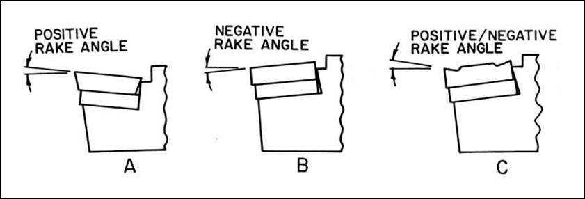
This configuration allows a
variety of inserts to be used in the same toolholder, which present negative,
neutral, or positive rake angles to the workpiece being cut. Here
is an example of the various types of insert topology available with different
rake angles and chipbreaker geometries.
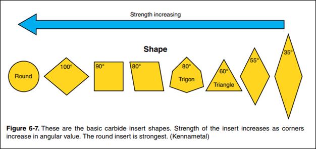
7.
Indexable insert strength. The following graphic illustrates the
relative strengths of various insert geometries.
8. Use
the right insert grade or prepare for disappointment. The correct insert grade (combination
of toughness and hardness, edge prep, chipbreaker and
coating) is imperative for decent tool life. Many people won’t take the
time to navigate the tomes of information and charts each quality cutting tool
manufacturer provides, so they buy the insert they read worked for someone else
or the one that’s available OTS from MSC since they order from them weekly (ehhh!). And the results are usually less than
stellar. The difference in proper grade selection can be 10 times the
tool life or more. Here is a nice short video discussing the benefits
of CVD vs PVD coatings.
9. Use roughing tools for roughing
and save finishing tools for finishing. Roughing inserts are designed differently tools are much
stronger than finishing tools because they have generous fillets or chamfers on
their cutting tips and serrated edges to break up chips into smaller pieces for
improved evacuation and less chance of re-cutting. Using one tool to
rough and finish wears it out much quicker, and often chips it before it even
gets to the finish passes. So using roughing tools
whenever possible actually reduces the total tooling cost for the job.
|
TURNING TOOLHOLDER SELECTION |
|||||
|
Tool Type |
Toolholder Style |
Insert Style |
|
|
Relative Strength (1 – 10) |
|
turning/facing |
CNMG |
CNMG43X |
|
|
8 |
|
profiling |
DNMG |
DNMG43X |
|
|
5 |
|
profiling |
VNMG |
VNMG33X |
|
|
3 |
|
parting |
MGIH |
GTN-3 |
|
|
2 |
|
parting |
SGFH |
GFR-3 |
|
|
3 |
|
|
|
|
|
|
|
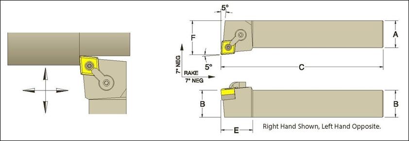
10. Select
the shortest tool / toolholder. When
selecting the toolholder, always choose the shortest length that allows
adequate tool clearance for the deepest depth cut and adequate nose clearance
for anything with which it could collide (a part wall, vise jaw, clamping
fixture, etc.). Worded another way: always select the stiffest
toolholder available that provides adequate working clearance.
Tool Loading [RETURN TO
T.O.C.]
1. Read and follow the Tool Selection guidelines posted previously so you
know exactly what type of tool you need (size, material, type, and length of cut) or you have specific
questions regarding what tools you need.
2. If you do not own a tool you
want to use or the tool is not already loaded in the machine, bring your setup sheet to Mike and ask for it. If you open the tooling drawers (to
see what’s available for use or to remove a tool), MAKE NOTES as to EXACTLY
where the tools or inserts (especially) came from and return them to the proper
storage location and box when finished making the part(s).
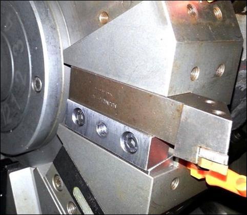
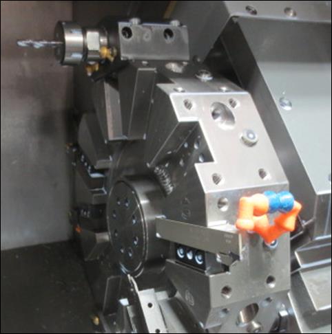
3. Be VERY careful of chuck jaw
clearance on adjacent tools and machine enclosure clearance on longer drills
that are loaded in the turret. It’s
typically necessary to stagger ID / OD cutting tools so adjacent tools do not
run into the rotating chuck jaws when another tool is trying to cut the
workpiece. Collet chucks do not have this problem, which is one of the
BIG reasons they are ALWAYS preferred to normal chucks.
a. Check for tool clearance by hand jogging the
turret forward to the maximum programmed negative Z travel from the Z zero to
ensure tools do not collide with the chuck jaws or the sheetmetal enclosure of
the machine.
b. Read the CNC
Cookbook Tips for Setting up a CNC lathe for more details.
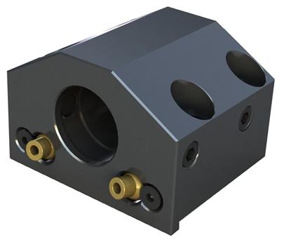
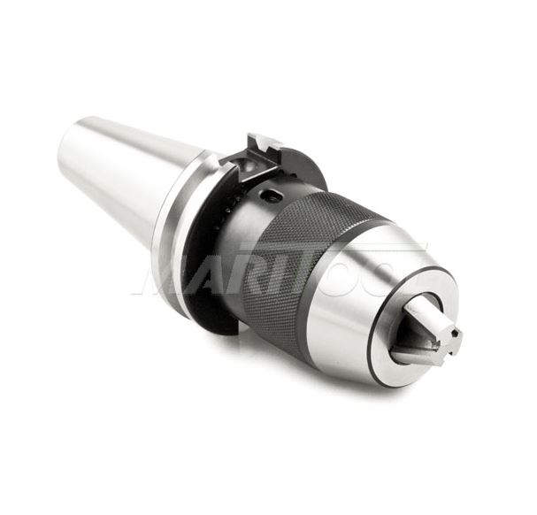
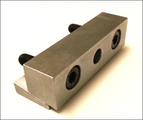
4. Use TOOL BLOCKS to install
drills / taps / reamers / boring bars
a. Clean each tool block’s mating surface before
each use. Always wipe off the
precision flat mating surface and remove any corrosion using a piece of
Scotch-Brite, a 400 grit stone, and a clean rag. If you have questions about how to clean a tool block, ask,
as loading a dirty or corroded tool block damages the turret.
b. Clean and stone the mating turret surface to
ensure there are no chips or dings.
c. Ensure the tool block alignment shoulder is
seated against the turret during installation.
d. After lightly tightening each fastener, use a
dead blow to seat the shoulder of the tool block against the turret.
e. Apply final tightening torque (50 lb-ft) to
the four tool block attachment screws. Three chuggas
with the Dewalt 3/8″ impact driver is adequate.
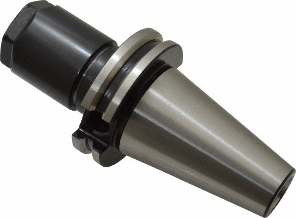
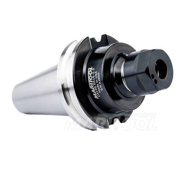
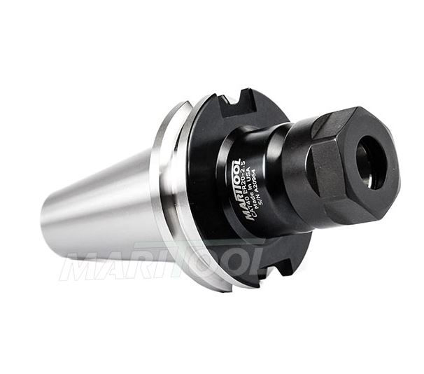
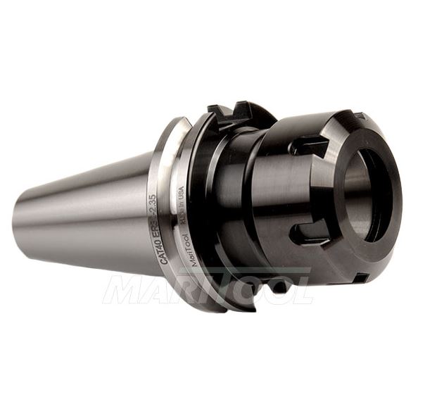
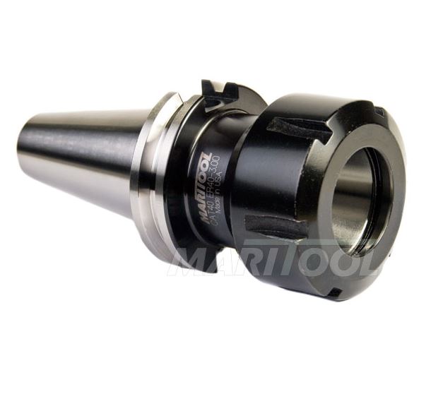
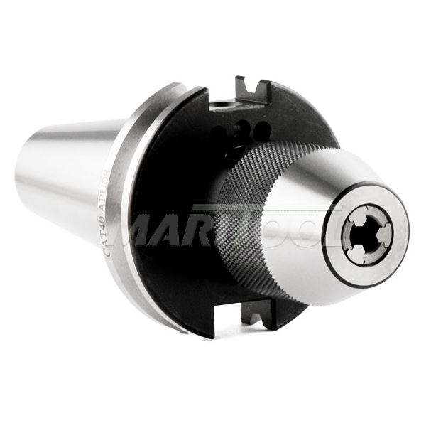
5. Select the appropriate type of
toolholder for on-center tooling and properly torque the collet nuts. Smaller series collet-style
toolholders have smaller nut diameters which allow for better coolant
application to the tool tip, but offer less clamping torque on the tool.
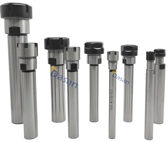
The
following table lists the type of toolholders we currently have in lab, the min
and max size tool shanks each type will clamp, the appropriate torque
specification, and the relative clamping strengths.
|
TOOLHOLDER CLAMPING STRENGTH COMPARISON |
|||||
|
Toolholder Style |
Min Clamping Diameter |
Max Clamping Diameter |
Nut Diameter |
Nut Torque (lb-ft) |
Relative Clamping Strength (1 – 10) |
|
1/16″ |
3/8″ |
0.85″ |
20 |
2 |
|
|
1/16″ |
3/4″ |
1.5″ |
60 |
3 |
|
|
1/16″ |
3/8″ |
1.1″ |
30 |
3 |
|
|
3/32″ |
1/2″ |
1.35″ |
60 |
4 |
|
|
5/32″ |
3/4″ |
2″ |
100 |
6 |
|
|
9/32″ |
1″ |
2.5″ |
130 |
8 |
|
|
1/8″ |
1″ |
0.8″ – 2″ |
snug J |
||
|
- |
- |
- |
- |
- |
- |
|
0.02″ |
5/16″ |
1.5″ |
N/A |
5 |
|
|
0.02″ |
1/2″ |
2″ |
N/A |
5 |
|
CAUTION: When installing tools in
ER-style collet chucks, always load the
collet into the collet nut BEFORE installing the collet nut onto the collet
chuck or
you will destroy the collet, nut, and toolholder.
6. Use WEDGE CLAMPS to install
tool holders for turning and facing tools (aka “stick tools”)
a. Lightly tighten the wedge screws against the
tool holder, use a dead blow to tap the tool holder flush with the turret, then tighten down on the wedge clamp
7. Tool Probing / Zeroing
a. Probe each tool length IMMEDIATELY
after loading, as forgetting to do so can result in
extensive tool and machine damage. If
you don’t have time to probe a tool, don’t load it, as the
consequence can be disastrous.
b. With the turret in the home position,
CAREFULLY lower the tool probe with both hands
c. In the Tool Offset Menu, ensure the proper X
or Z offset register is highlighted before zeroing (press Offset to
cycle through the different offset menus). For example, when probing the
Z tool offset for a turning facing tool that is in slot number 1, highlight the
Z offset in the same row as tool number 1.
d. CAREFULLY hand jog the tool within 0.1″ of the
probe in either the X or Z direction (whichever side you are zeroing), select
the 0.001 or 0.0001 increment, and press and hold the directional arrow to move
the tool until it touches off on the probe.
e. You will hear a beep that confirms the tool
has been zeroed, and the tool will stop advancing.
f. CAREFULLY back off the
tool probe using the directional arrows. Once you reach a safe distance and the
tool probe has been put away, send the turret home (G28)
g. When probing tools, understand the
wear offsets are automatically reset to zero. This means
if you had a wear offset previously, you won’t any longer J.
h. Tool Tip Type
i. Tool Tip Type defines the orientation in
which a tool was zeroed, as if you were looking down onto the top face of the
probe.
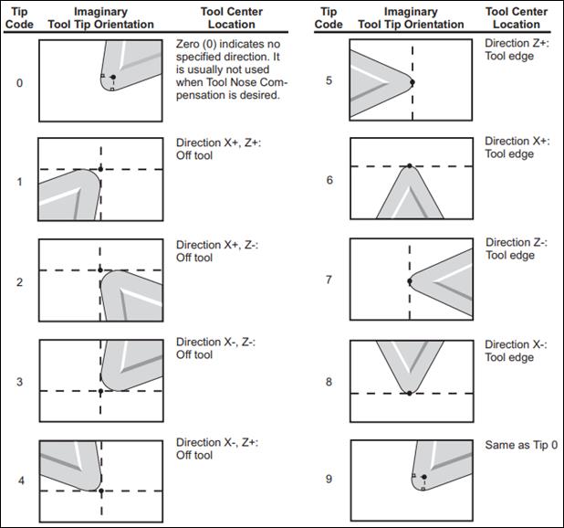
ii. Turning and Facing Tool: Tip Type 3
iii.
Drills: Tip Type 7
iv. Part Off Tool (Zero on TSS): Tip Type 4
v. Part Off Tool (Zero on HSS): Tip Type 3
vi. Boring Bar: Tip Type 2
i. Multiple Offsets for One Tool
i. Programming for part-off tools often benefits
from having two zeros: one on the headstock side of the tool and one on the
tailstock side of the tool.
1. Headstock Side (HSS) – T1111
2. Tailstock Side (TSS) – T1121
8. Put tools away when done. When you are finished with your part,
unload any tools you loaded, returning the tools to their appropriate
containers and to Mike for storage, and return toolholders and collets to their
respective carts or drawers. Failure to do so will result in suspension
of CNC use privileges, because it’s disrespectful and that’s how tools are lost.
Work Holding [RETURN TO
T.O.C.]
Always hold the part using the
safest workholding available, which
means a collet chuck if possible, otherwise a chuck.
1. Clamping Pressure Adjustment
a. Always adjust the clamping pressure
BEFORE loading the part into the chuck using the clamping pressure chart and
gage on the tailstock side of the machine.
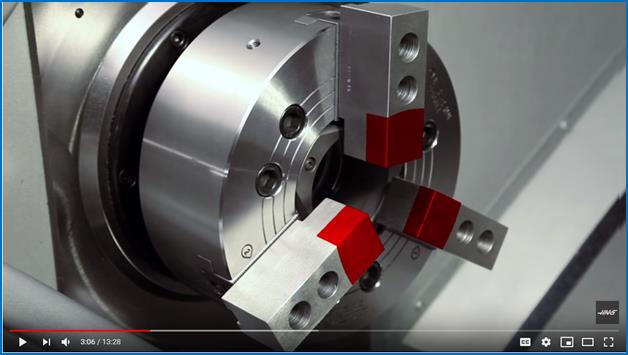
2. 3 Jaw Chuck
a. Before continuing, watch the following video
on changing lathe chucks:
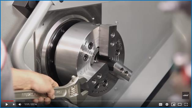
b.
Use the cordless Impact driver
with the correct size allen drive socket to loosen
(but not fully remove) the chuck jaw bolts so you can adjust their position on
the mating serrations.
i. CAUTION: It is imperative that each
chuck jaw is the same radial distance from the center of the chuck. Count the number of serrations, and ensure
that the number of serrations from an edge are the same.
ii. Always
ensure the jaws clamp the part within the travel indicator marks of the master
jaws:

iii. Ensure the chuck jaw screws are
properly torqued (50 lb-ft) before continuing. If you forget to tighten the chuck jaw
screws the results can be catastrophic, so always be explicit about doing so.
iv. Always start the spindle slowly in
MDI to check new workholding. If
you make a mistake setting up the workholding or programming a spindle speed,
the result can be catastrophic because of how quickly the machine can
accelerate the chuck to 6k rpm. Always check
your workholding at 250 or 500 rpm before running higher speeds (S500 M03 in MDI mode) and always program a safe spindle speed
clamp (G50 S250 or S500).
c. When necessary cut soft jaws for proper part
clamping, as shown in the following exceptional video and use a carbide insert
with extremely high toughness (versus hardness):
3. Collet Chuck
a. NEVER PLACE A COLLET IN THE COLLET
CHUCK WITHOUT A PIECE OF MATERIAL IN THE COLLET. If the collet chuck is actuated on an
empty collet, the collet will be crushed. In addition, the collet chuck
actuates on shutdown (or power loss) as a safe state, so that’s the second reason
to never load an empty collet.
b. There is a special tool for loading /
unloading collets so you do not cut your hand from the sharp collet edges.
4. Live Centers
a. Whenever possible, use a live center in the
CNC lathe because of the risk of ejecting a part at the higher spindle speeds
achievable on these machines.
5. G50 Spindle Speed Clamp
a. ALWAYS program a safe spindle speed
clamp (max allowable speed) when using G96 (constant surface speed
mode).
b. When using a conventional 3 or 4 jaw chuck, the speed clamp should be set LOWER FOR LARGER AND/OR
LONGER PARTS due to the
inherent reduction in clamping force and increase in rotational inertia
inherent at higher spindle speeds.
c. When using a collet chuck, the speed clamp
should be set LOWER FOR SMALLER DIAMETER AND/OR LONGER PARTS (AND PART STOCK) due to the inherent reduction in part
stiffness, which promotes whipping / buckling inside the spindle drawtube at
higher spindle speeds.
Setting Work Offset [RETURN TO T.O.C.]
After
loading the workpiece using the information presenting in the work holding
section of this page, the next step is to set the work offset, which is
typically performed by touching off on the part while it is slowly rotating.
1.
Safely send the turret
to the HOME position and switch to T0101 (the turning/facing tool).
2.
Turn the spindle ON FORWARD at a
safe speed: MDI >> G97 S500 M03
3.
Carefully hand jog the X and Z
axes to bring the turning and facing tool (T1) close to the face of the
workpiece (using 0.1″ jog
increments)
4.
Decrease the increment size to
0.001″/handwheel pulse and GENTLY touch off on
the face of the workpiece
5.
Record the current position as
the work offset: Offset >> G54 >> Highlight the Z coordinate >>
Z Face Measure
6.
Carefully hand jog away from the
face of the part by SLOWLY
rotating the dial CLOCKWISE (Z+ direction), and then send the turret
home by pressing HOME (G28)
7.
Offset Z-offset by -0.010″:
Offset >> G54 >> Highlight the Z coordinate >> Type -0.010 >> press Enter
Graphics/Simulation [RETURN TO T.O.C.]
1.
Always check the
program using graphics until you are confident you understand EVERY single move
each tool will make. Use a
combination of single step mode, work coordinates, and distance to go to
troubleshoot any programming issues. If you don’t
understand why a particular motion is taking place, DO NOT CONTINUE to the next
step.
2.
Always start graphics
verification the same was you run any CNC machine: with the RAPID turned down
to 5% and one finger on the FEED HOLD button, because there is a fundamental design error on Haas CNC lathes
that allows the user to run the machine instead of the graphics simulation if
ONE keystroke is out of sequence. So expect about one out of 100 times,
you will make this mistake, and the ONLY way you will catch it in time is if
you have the RAPID turned down to 5% and a finger on FEED HOLD EACH TIME.
3.
To enter graphics: Edit >>
Setting Graph x2
4.
Press F4 to display the
active code in the bottom right corner of the simulation window
5.
Press F2 and use the PAGE UP/PAGE
DOWN to zoom in/out on the toolpath, and use the arrow keys to move the
magnified area; after sizing the area of interest, press Enter
6.
With your left hand on the Feed
Hold, press Cycle Start to begin the simulation; press Feed Hold
to pause the toolpath if necessary
7.
Enable Single Block to
execute one block of the program for every press of Cycle Start
Dry Run (aka Test Run) [RETURN TO
T.O.C.]
1.
A replacement SL-10
costs about $80k.
Remember this value because that’s how much it can cost to fix a SERIOUS
mistake if you don’t pay attention to the rest of this document.
2.
When ready to test the program, remove
the workpiece if using a chuck or move the work flush with the face of the
collet so you can test the program in air.
3.
Home the turret so it
is at the safest tool change position.
4.
Set the RAPID override to 5% (which is still very fast on a CNC lathe when
close to the chuck, so be careful). You can
use 25% for tool changes in the turret HOME position, but slow it back down to
5% before approaching the part.
5.
Reduce the SPINDLE SPEED OVERRIDE
and FEED OVERRIDES as necessary to SAFELY approach the chuck / workpiece.
6.
Open the program in the machine
editor, press the RESET button, and go into MEM mode.
7.
With your left thumb on
the green CYCLE START button and your right thumb on the red FEED HOLD button,
begin the program by pressing CYCLE START and pause the program by pressing the
FEED HOLD BUTTON.
8.
Adjust the RAPID to 5%
ANYTIME you are within 6 inches of the part to ensure the tool doesn’t rapidly move towards the part or chuck
jaws.
9.
As each tool is moving
into position, carefully check tool clearance of the current tool, adjacent
tool(s), and any longer tools that are installed on the turret (long tools can hit the back wall of the
machine enclosure).
10. Be sure to home the turret at the
end of each dry run so there is ZERO chance that you will accidentally run the
program with a tool in the same zip code as the chuck.
First Part Run (aka Prototype
Run) [RETURN TO T.O.C.]
1.
Safely HOME the turret.
2.
Set the RAPID override to 5% (which is still very fast on a CNC lathe when
close to the chuck, so be careful). You can
use 25% for tool changes in the turret HOME position, but slow it back down to
5% before approaching the part.
3.
Set the SPINDLE SPEED
to 60% and the FEEDRATE to 40% overrides.
4.
Run the first tool, being very
cautious to FEED HOLD if anything LOOKS, SOUNDS, FEELS, or SMELLS wrong!
5.
If everything seems fine, monitor
spindle speed and chipload on CURRENT COMMANDS screen
and progressively bring overrides up to 100%.
6.
Reset SPINDLE SPEED
(60%) and FEEDRATE (40%) overrides for each new tool used in your program and
repeat steps 4 and 5.
Production Run [RETURN TO
T.O.C.]
1.
If ANYTHING is changed in the
program, you must re-prove the associated portion(s) of the program and tool(s)
involved.
2.
If you don’t CRITICALLY measure
EVERY important feature on your last part, you will quickly generate a lot of
scrap parts. Because
of human error, it’s always good practice to ask another person whose metrology
skills you trust to use the accurate and clear detailed drawing you created
previously to check each important feature on your last part.
3.
Understand tools wear, so it’s
necessary to inspect parts as they come off the machine during production runs.
Cleanup [RETURN TO
T.O.C.]
Do not leave
the machine dirty overnight, as doing so is disrespectful. If you value the privilege of using the CNC
lathe, show it by leaving the machine spotless.
1.
Protect your ears
during cleanup. Wear
hearing protection when cleaning the machines since the air is unregulated
(full pressure) and consequently very loud. Call EARS prior to use for
others in the area.
2.
Use the compressed air to blow
chips from the top down: start with
the turret, then the chuck, and finally the way covers. GENTLY blow the
coolant and chips inside the machine from the tailstock chip pan (outside the
machine on the tailstock side).
3.
Remove DRY chips (once the
coolant has time to drain overnight) and place in the red refuse can labeled
CNC CHIPS. Use the work gloves on
top of the machine because the chips will be SHARP and
will (seriously) cause lacerations, so don’t play around here.
4.
Carefully return the turret HOME
and index the turret back to position #1 before turning the machine OFF by pressing Power OFF.
Important Points [RETURN TO
T.O.C.]
1.
NEVER run the CNC while
talking to or with another person. FEED HOLD, carry on your conversation, instruct them to be
quiet if you are okay with them watching, REFOCUS your attention, and only then
continue.
2.
NEVER run the machine
with the door open or stand in the plane of the rotating chuck jaws. People have been killed when
a programming error caused a tool to move rapidly into the rotating chuck jaws,
shearing the attachment bolts, and flying out of the machine.
3.
Always start the
spindle slowly in MDI to check new workholding. If you make a mistake setting up the
workholding or programming a spindle speed, the result can be catastrophic
because of how quickly the machine can accelerate the chuck to 6k rpm. Always check your workholding at 250 – 500 rpm before running
higher speeds and always program a G50 SXXXX spindle speed clamp
(limit).
4.
Never press the
ENTER button on the controller without knowing what you are doing. If you mistakenly do so while editing
a program, that data will overwrite whatever line is highlighted in the
program, causing a potential crash when your run the program.
5.
Ensure the correct
memory offset register is highlighted before probing tools or the value will
NOT be recorded. The
Haas machine has a bug where you can probe a tool without the offset data updating
if you are not in the correct screen and highlighting the correct offset
variable.
6.
Understand the
SL-10 is not a very rigid platform compared to higher-end M-brand Japanese
turning centers, and as such you need to use the proper machining strategy. Namely, lighter depths of cut and
higher spindle speeds (as long as your tool selection will allow it. The
basic strategy should be to increase the depth of cut until you encounter
chatter; then increase your feedrate and spindle speed (in that order) until
tool life suffers. At that point you will have the optimal parameters for
the operation.
Bonus Stuff [RETURN TO
T.O.C.]
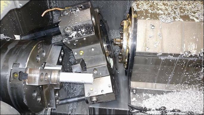
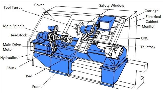
Slant-bed CNC 2-axis CNC lathe shown without
covers:
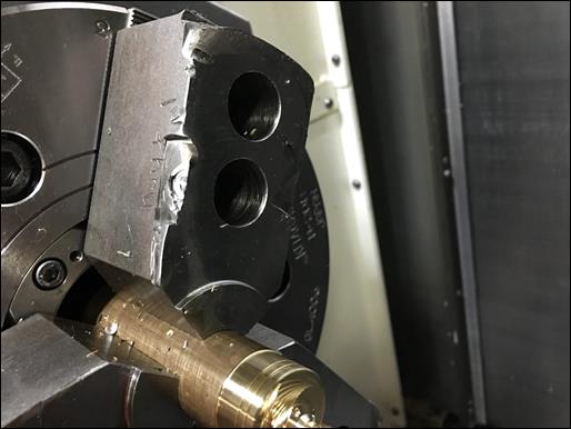
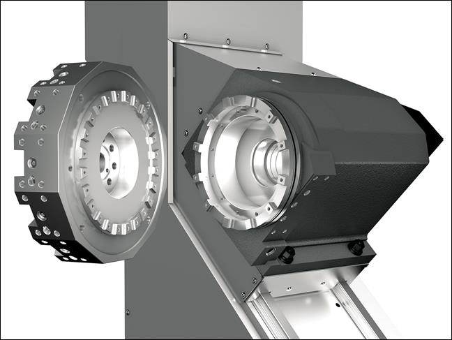
Typical CNC lathe turret curvic
coupling:
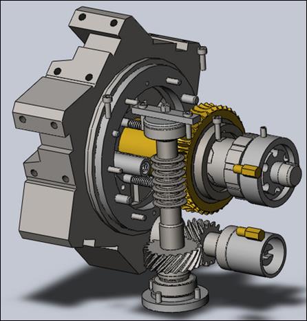
Typical CNC lathe turret drivetrain:
Machine Manuals and Reference
Documents [RETURN TO T.O.C.]
Haas
SL-10 Control Book Exercises
Haas
SL-10 Programming Workbook