USE OF INDICATORS
Introduction
Indicator is
a generic name given to a device that provides information on the state or
condition of something. In a
manufacturing environment an indicator typically refers to a measurement
instrument that provides position feedback via an analog or digital
display. Indicators have many uses in
the shop, and the purpose of this document is to illustrate a few of the more
common applications.
In the most
general sense, there are two types of indicators commonly used in shop
environments: test indicators and drop indicators. As shown in figure 1, a test indicator uses a
tilting lever arm to measure an artifact moving underneath its stylus, whereas
a drop indicator uses a linear motion to measure a part moving underneath its
plunger).
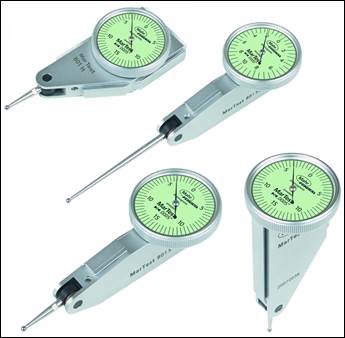
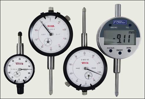
Figure 1:
Assortment of dial indicators: test-style indicators on left and drop-style
indicators on the right.
Indicators
are prone to at least two common error sources resulting from the mechanics of
how they work. One is cosine error, as illustrated in figure 2 below. This
error is particularly likely with a test indicator, which is the type of
indicator that uses a tilting lever arm to measure a part moving underneath it
(as opposed to a drop indicator, which has a linear plunger). In a correct
measurement setup, the lever arm is adjusted so that the movement of the tilt
is as close as possible to being perpendicular to the measured surface. For this reason, drop indicators are
preferred for measuring parts which vary largely in height.
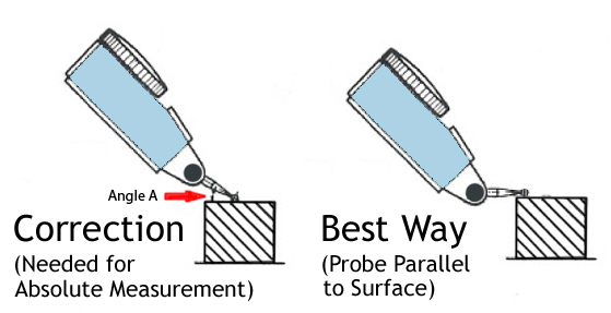
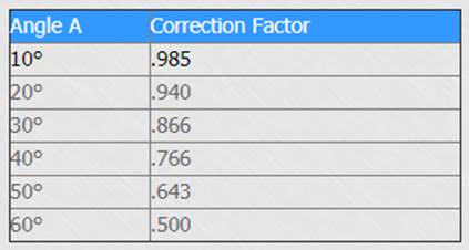
Figure 2:
Cosine error illustrated and quantified.
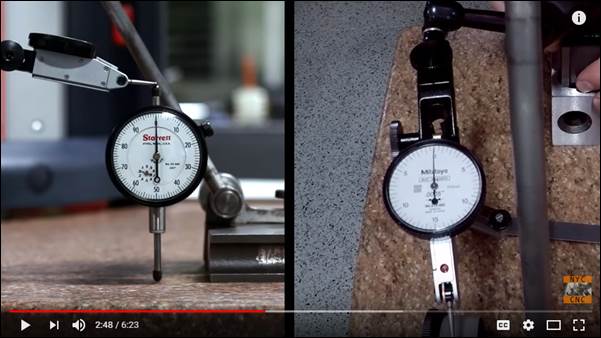
Figure 3:
Cosine error video by John Saunders.
The other
error common for indicators is hysteresis. This term refers to a lag between
action and reaction in a mechanical system. An example of hysteresis is the
“play” that may be detectable in a car’s steering wheel. The steering wheel
turns a tiny amount before the car’s wheels begin to change direction.
Indicators have this play, too. As precisely as the indicator may have been
made, it still needs some clearance between gear teeth. If you push the plunger
of a dial indicator up from its rest position, there will be a very short
duration during which the plunger is moving but the gear that moves the
indicating hand on the dial face has not yet begun to move.
How often is a dial indicator moved along a surface
to measure a taper or step? There will be hysteresis error in any such
measurement because of the small delay before the indicator’s movement causes
the indicator hand to move. The error is very small, but the point to remember
is that errors compound. An error allowed at calibration, combined with cosine
error, combined with hysteresis, combined with a part not being cleaned
sufficiently, can create more error than most would suspect.
Common Indicator Uses
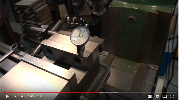
Figure 4: Using a test indicator
to indicate a milling machine vise [video].
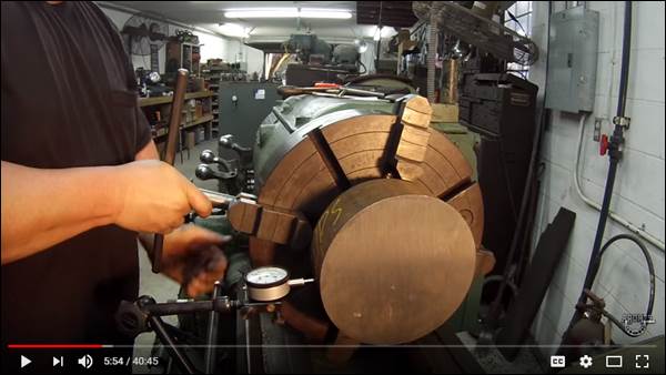
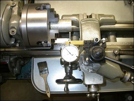
Figure 5: Indicating a
cylindrical part in a 4-jaw chuck, from the best guy in the business (i.e.
watch the video and subscribe to his channel if you want to learn a lot)!
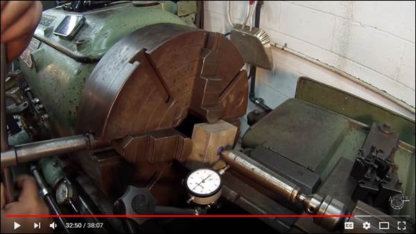
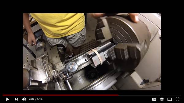
Figure 6: Crafty methods for
indicating rectangular parts in 4-jaw chucks [videos]!
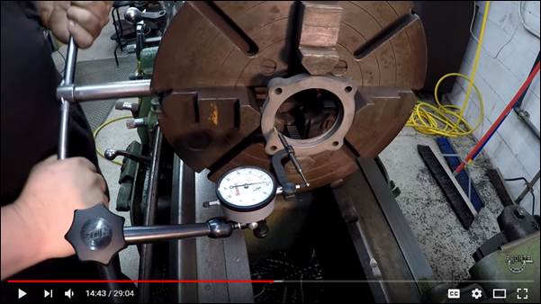
Figure 7: Using a drop indicator hole attachment [video].
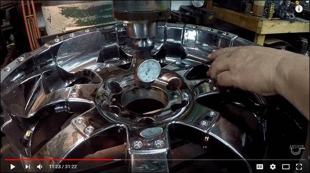
Figure 8: Using a co-axial
indicator to find the center of a precision bore on the mill [video].
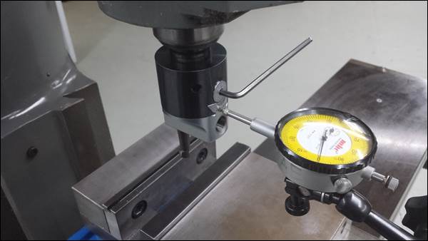
Figure 9: Dial indicator used to
precisely adjust boring head on mill.
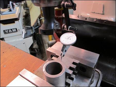
Figure 10: Dial test indicator
used to precisely locate part center on mill.
Indicator
Application Tips
1.
Indicators
are available in a variety of resolutions (i.e. 0.001”, 0.0005”, 0.0001” per graduation).
Select the lowest resolution indicator that will work for your
application, because it will also be the cheapest.
2.
Treat any
indicator with the utmost respect, as dropping it or rapidly accelerating the
plunger or stylus will ruin the accuracy of the indicator. Since accidents happen, please let Mike know
so he can test and replace the indicator if necessary.
3.
Make sure
the part surface you are indicating is clean and smooth before running the
indicator plunger or stylus across it. For example, when tramming
a vise, clean the non-moveable jaw with a piece of Scotchbrite to remove any smeared chips or corrosion.
4.
If using an
indicator stand, select the shortest, stiffest base possible and don’t waste
your time or money with anything other than NOGA designed
indicator holders.