Electric DC motors (type, function and application to
robots)
Types of Motors:
Electric motors are the most common device for converting electrical energy into mechanical power. The type of power supplied and mechanical requirements of the application are factors that must be considered when choosing which type of motor to use. The common types of electric motors are:
The most general classification for electric motors is according to the type of power supplied: AC or DC. AC stands for alternating current, which is the type of power produced in an industrial power plant and distributed to commercial and residential buildings via high voltage power cables. DC stands for direct current, which is the type of power produced by a battery. Since the robot requires wireless mobility, a battery supplies the power; therefore, DC is the only type of motor suitable for use with the course project. Consequently, the remainder of this research will pertain only to DC motors.
Brushed DC Motors: [RETURN TO TOP OF PAGE]
The simplest type of electric DC motor is the brushed type motor. As shown in figure 1 below, brushed DC motors typically have six parts: an armature (or rotor), commutator, carbon brushes, axle, field magnet and DC power supply. Electric motors rely on the principle of electromotive force for their operation. The field magnet inside an electric motor creates a magnetic field characterized by a north and a south pole. When voltage from a battery is applied to the coil of wire wrapped around the rotating armature, a second magnetic field is created. These two magnetic fields react against one another, creating attractive or repulsive forces, resulting in a small rotation of the armature about its axis. At this point, the armature would “lock” into position just like bringing the opposite poles of two magnets into contact. To prevent this, the voltage polarity is reversed (via the commutator and brushes), which results in the armature’s magnetic field reversal. This causes the armature to rotate 180 degrees, at which time the source DC polarity again reverses, causing the armature to turn another half rotation.
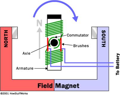
Figure 1: Brushed
(aka Permanent Magnet) DC Motor Illustration
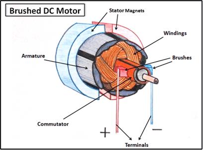
Figure 2: Brushed DC Motor Cutaway View
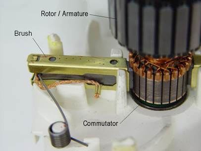
Figure 3: Brushed DC Motor Commutator, Brushes and Armature
The brushed DC motor is one of the oldest motor designs, being in commercial use since the late 1800’s. Due to their inherent simplicity, low cost and ability to control speed and torque easily, DC motors are a popular motor choice for many applications. On the other hand, there are a number of drawbacks to the brush and commutator mechanism used in a brushed motor: the brushes cause friction; there is some electrical resistance in the brush-to-commutator interface; and the mechanical switching of the armature current results in sparking, which can cause radio interference or explosions (saw mill or chemical plant). [Source: Stefanv]
Video 1: DC Electric Motor
Video 2: Brushed DC Motor Basics Part 1 of 2
Video 3: Brushed DC Motor Basics Part 2 of 2 (up to 1:44)
Video 4: Brushed DC Motor Explained (Excellent)
In closing, here are the specifications for the (permanent magnet brushed-type) electric motors we have for use in the lab. Permanent magnet brushed DC motors are the only type of electric motor compatible with the course robotic controllers.
Brushless DC (BLDC) Motors: [RETURN TO TOP OF PAGE]
The brushless DC (BLDC) motor operates on the same principles as a brushed type DC motor; however, the permanent magnet and electromagnet parts of the motor are swapped, as shown in figure 4 below. In contrast to a brushed DC motor, a BLDC motor has one or more sets of permanent magnets that rotate (called the rotor) and a stationary armature (called the stator). Since the electromagnet part of the BLDC motor is fixed, the problem (existing in brushed type motors) of connecting current to a moving armature is eliminated.
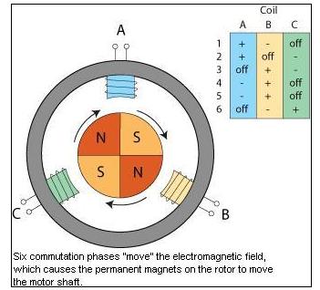
Figure 4: Brushless
DC Motor Illustration
External circuitry monitors the current position of the rotating magnet and energizes the external (stator) magnets to keep the motor turning. This circuitry is part of the brushless electronic speed control (ESC). The brushless ESC monitors rotor position using magnetic sensors and the Hall-effect. These sensors report back to the ESC. Stated another way, the brush/commutator assembly of the brushed DC motor is replaced by an electronic controller which continually switches the phase to the windings to keep the motor turning. The controller performs similar timed power distribution by using a solid-state circuit rather than the brush/commutator system.
BLDC motors have been in commercial use since the early 1960’s. BLDC motors offer several advantages over brushed DC motors, including more torque per weight; improved efficiency and reliability; reduced noise (electromagnetic interference); longer lifetime (no brush and commutator erosion); elimination of sparks from the commutator; and power. Finally, because the windings are supported by the housing, they can be cooled by conduction, rather than by airflow (convection) through the motor housing. This means the motor's internals can be entirely enclosed and protected from dirt or other debris.
The maximum power that can be applied to a BLDC motor is exceptionally high, limited almost exclusively by heat, which can weaken the magnets (Neodymium-iron-boron magnets typically demagnetize at temperatures lower than that of boiling water). The primary disadvantage to BLDC motors is higher cost due to the complex electronic speed controllers required for operation. In contrast, brushed DC motors can be regulated by comparatively simple controllers, such as variable resistors (however, this reduces efficiency because power is wasted).
In conclusion, BLDC motors are often more efficient at converting electricity into mechanical power than brushed DC motors. This improvement is largely due to the absence of electrical and friction losses due to brushes. The enhanced efficiency is greatest in the no-load and low-load region of the motor's performance curve. Under high mechanical loads, BLDC motors and high-quality brushed motors are comparable in efficiency. In general, manufacturers use brush-type DC motors when low system cost is a priority but brushless motors to fulfill requirements such as maintenance-free operation, high speeds, and operation in explosive environments where sparking could be hazardous.
Since the robotic controllers for EML2322L do not contain sophisticated electronic speed controllers, brushless motors cannot be used with the course project.
Servo Motors: [RETURN TO TOP OF PAGE]
A servo motor (or just servo) is a motor that uses error-sensing feedback from one or more sensors and external circuitry to correct the output of the motor. For example, SLR cameras requiring the user to manually focus the lens are not servomechanisms because there is no automatic feedback (and microcontroller) that controls focus (i.e. lens position)—the operator does this by observation. In contrast, auto-focusing cameras use closed-loop feedback--meaning the controlled parameter (in this case, lens focus) is sent back to the motor to allow its position to automatically vary in relation to the lens focus. An automotive example would be a power window motor control switch, which requires manual feedback from the operator, versus a cruise control module, which regulates throttle position automatically by measuring vehicle speed and correcting without user intervention.
Servos are common on airplanes and boats (both model and full-scale), automatic machine tools, satellite tracking antennas, antiaircraft gun control systems and modern hard disk drives, among others. Since the robotic controllers for EML2322L are not capable of receiving position feedback, servo motors cannot be used with the course project.
Stepper Motors: [RETURN TO TOP OF PAGE]
A stepper motor is a brushless electric motor that converts digital pulses into mechanical shaft rotation. Every revolution of the stepper motor is divided into a discrete number of steps (in many cases 200 steps) and the motor must be sent a separate pulse for each step. The stepper motor can only take one step at a time and each step is the same size. Since each pulse causes the motor to rotate a precise angle (typically 1.8°) the motor's position can be controlled without any feedback mechanism. As the digital pulses increase in frequency, the step movement changes into continuous rotation, with the speed of rotation directly proportional to the frequency of the pulses.
Stepper motors are used every day in both industrial and commercial applications because of their low cost, high reliability, high torque at low speeds and a simple, rugged construction that operates in almost any environment. [Source: Omega Engineering]
Since stepper motors require an amplifier capable of generating variable frequency pulses, and the controller for EML2322L is only capable of outputting a voltage between ±12VDC, stepper motors cannot be used with the course project.
Figure 6: Modern Stepper Motor Construction
Linear Motors or Actuators: [RETURN TO TOP OF PAGE]
As the name implies, linear motors is a general classification used to describe electric motors (or mechanisms) that produce linear motion as opposed to rotary motion. Linear motion is accomplished with either a “real” linear motor or a screw-type mechanism that converts traditional rotational electric motor output to linear motion. A “real” linear motor is a motor that has its stator “unrolled” so that instead of producing a torque (rotation) it produces a linear force along its length, as shown in Figure 7 below. Alternatively, a threaded rod and nut can be used to convert the rotational motion of a traditional electric motor into linear movement; this is typically referred to as a linear actuator and can be seen in figures 8 through 10.
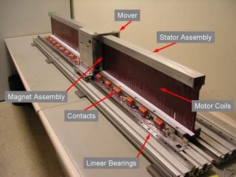
Figure 7: ”Real” Linear Motor
Figure 8: Typical Linear Actuator
(Cutaway Model for Clarification)
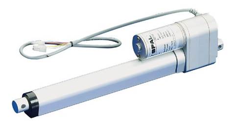
Figure 9: Complete Linear Actuator
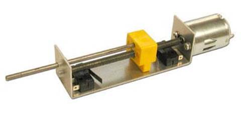
Figure 10: Another Linear Actuator Design
Here is a comparison of different motor types. This is useful when trying to compare the benefits of different motor types to select an appropriate motor for a particular design.
Any linear motor which uses a permanent magnet brushed DC motor is compatible with the robotic controllers for EML2322L and thus suitable for the course design project.