Abrasive Water Jet (AWJ)
1.
Introduction
2. Manuals
a.
FlowPATH
b.
FlowNEST
c.
FlowCUT
3.
Generating Cutting Path (i.e. Part
Program) using FlowPATH
4.
Combining Cutting Paths for Multiple
Parts using FlowNEST
7.
Cutting the Part using FlowCUT
9. Design
Tips
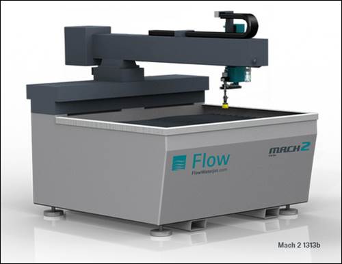
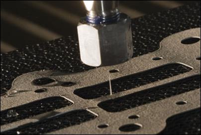
Introduction [RETURN TO TOP]
This document is intended
to train TAs on how to use the lab’s Flow Mach2 Abrasive Water Jet cutting
machine. Here
is a condensed quick start version of this document for printing.
Generating
Cutting Path (for Single Part) using FlowPATH [RETURN TO TOP]
1.
Turn ON main machine power switch on the back side of the
machine. This initiates the computer
boot sequence (the typical Windows start process).
2.
Insert USB storage device into the extension cable on the
front of the computer (this cable prolongs the life of the machine USB port).
3.
Open FlowPATH AWJ path trajectory
generation software.
4.
Load the .dxf (drawing exchange format) or .dwg (drawing) file from USB
device.
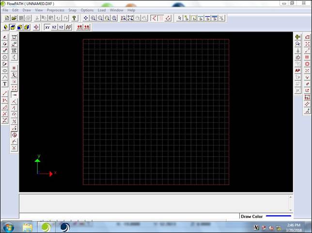
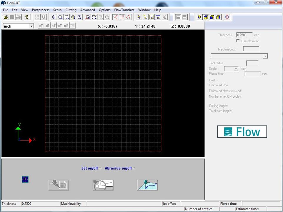
5.
Understand the workspace lines.
a.
The red-dotted square is the maximum cutting area (i.e. the
table size ~51x51”).
b.
The white grid squares (2”x 2”) represent the current
coordinate system (similar to G54). Bottom left is (0,0) (similar to G28)
c.
Solid lines are cut paths (various colors)
d.
Blue dotted lines are transverse (non-cutting) paths
6.
Delete all unnecessary lines and comments imported with the
.dxf.
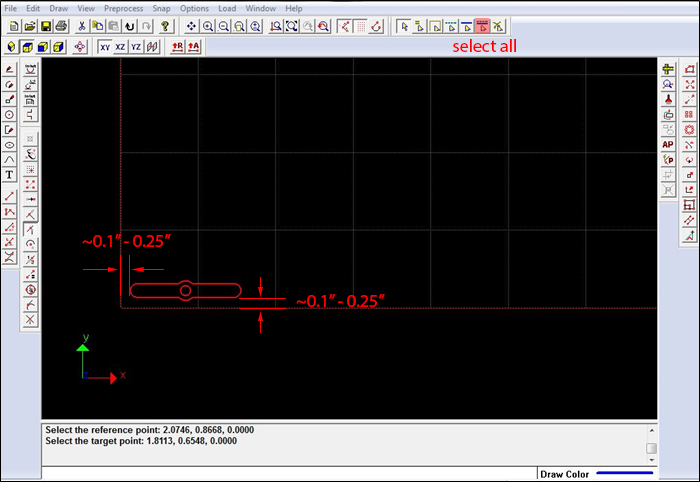
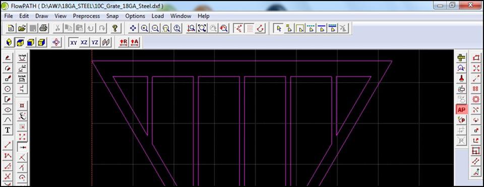
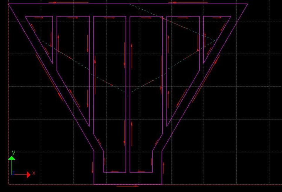
7.
Select all (top right
menu bar or Ctrl-A) and Move (right
menu bar) the part model to bottom left corner of white grid with ~0.1-0.25” of
clearance along X and Y axes.
![]()
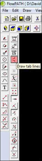
8.
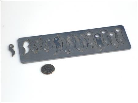
OPTIONAL: For small, thin, or long parts, tabs should be added to ensure the
parts don’t deflect while being cut, rotate upward into the trajectory of the
cutting nozzle, or fall into the catch tank.
If in doubt, always add tabs to the part to prevent expensive machine
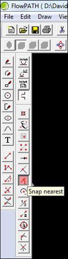
damage. Add tabs to your part by first clicking on
the Draw Tab Lines icon, then the Snap Nearest icon on the left hand side
of the screen.
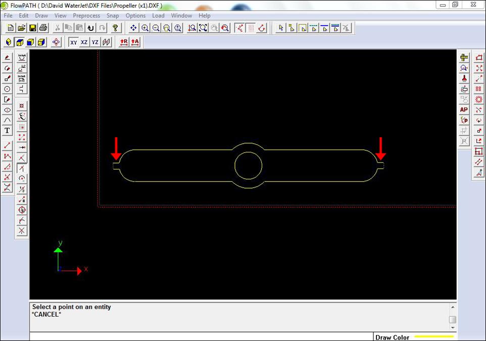
a.
Click along an outside edge to place the tab, and make sure
that the tab is facing the proper direction (shown below)
b.
If the color of the tab cut lines are not consistent with
all other cut lines, the following section on adjusting cutting speeds will
correct this
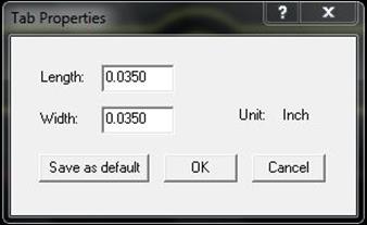
c.
To adjust tab properties select Draw à Tab Properties and modify the length and width of the tab as needed
9.
Adjust cutting speeds.
a.
Select all
cutting lines and click appropriate cutting speed from bottom menu bar
i.
40-60% for tight tolerances or nice edge surface finishes
ii.
80-100% for looser tolerances and no crucial edge surfaces
(sheetmetal parts)
![]()
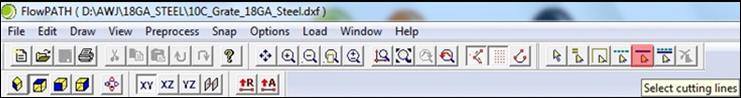
b.
If there are any traverse lines that should
be cut lines, select the line(s) then click the appropriate cutting speed from
the bottom menu bar
![]()
10. Autopath and adjusting
transverse lines.
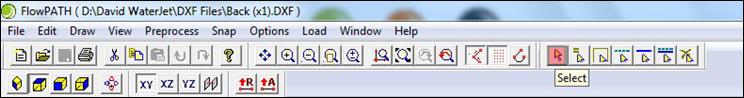
a.
Select all (Ctrl-A) lines
b.
Click Autopath (AP) from right menu bar
c.
Check path offset
i.
Ensure cut path is on the inside of internal features (like holes)
ii.
Ensure cut path is on the outside of external features (like the part profile)
iii.
If it’s not, good luck changing it J
d.
Check lead-in/out lines
i.
Linear parts should have straight leads on corner, if
possible, to prevent cusp
ii.
Curved parts benefit from having arc leads
iii.
Setting must be changed before auto-pathing (UNDO if needed)
e.
Check traverse lines
i.
CAUTION: NEVER TRAVERSE OVER PREVIOUSLY
CUT PART LINES IF POSSIBLE, AS DOING SO CAN BREAK THE EXPENSIVE CARBIDE MIXING
TUBE IF THE PREVIOUSLY CUT PART TIPS UP INTO THE PATH OF THE MOVING WATER JET
NOZZLE
ii.
Drag lead-in/outs when necessary to suitable location: Edit → Drag Lead-in/out
11. Once path
set-up is complete, use File → Export Path as…
to save file as .ORD.
a.
Do not save the FlowPATH file / session
b.
Do not use “Export 5.x Path as…” (this is an older file
version)
Nesting Multiple Parts using FlowNEST [RETURN TO TOP]
1.
To cut multiple parts from a single piece of stock, an .ORD
file should be generated for each part.
(Multiple parts can be placed in the same .dwg
or .dxf file, however Autopathing doesn’t always work well in those instances, so
we recommend using Flow’s nesting software.)
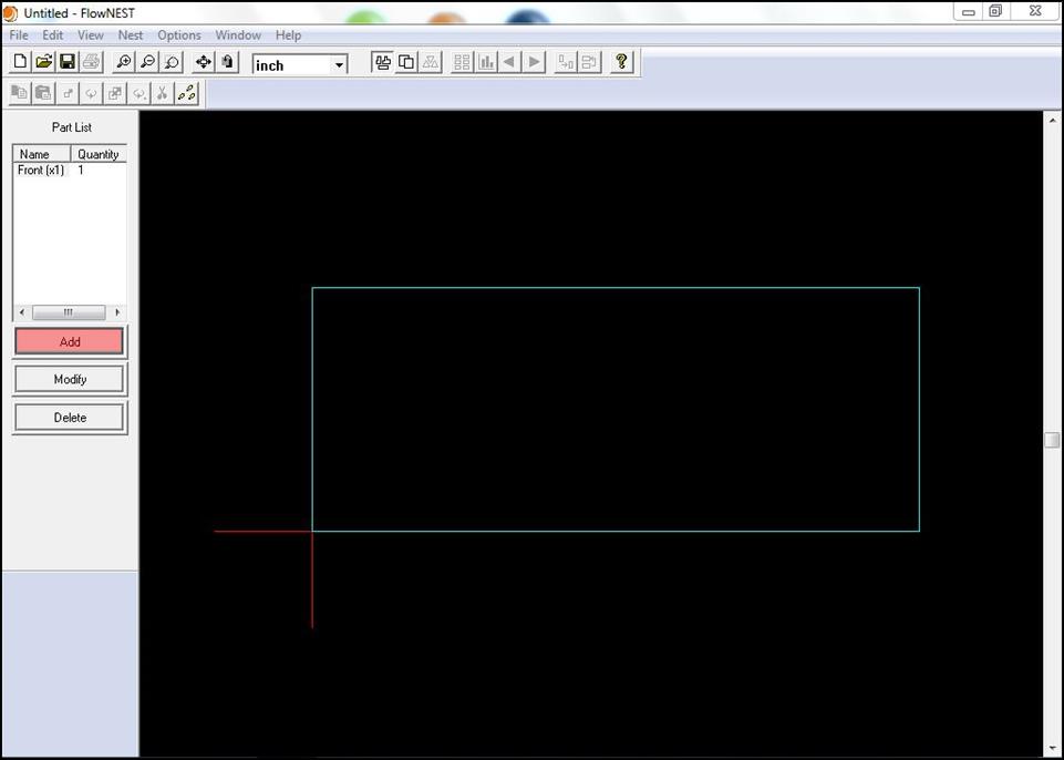
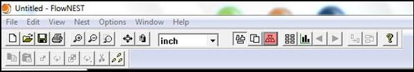
2.
Open FlowNEST.
3.
Select Edit →
Part Data or click the Part Data
icon to begin the part selection process.

a.
Select Add to
display the Part Data dialog box
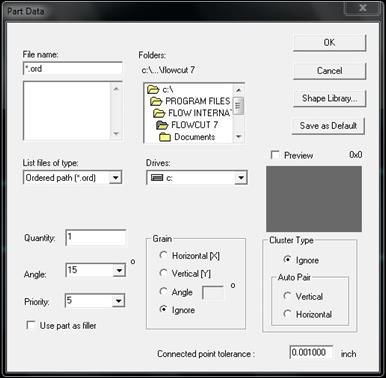
b.
In the Part Data dialog box, adjust the quantity of each
part as needed and leave the other parameters as the default unless you’re
feeling adventurous J
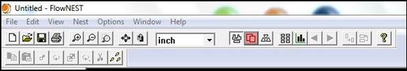
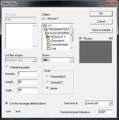
4.
Select Edit →
Sheet Data or click the Sheet Data
icon to select/define the stock from which the parts will be cut. Select
Add to open the Sheet data.
a.
Select Use the
rectangle defined above and enter the length and width
b.
NOTE: The stock size you enter should be smaller than the
size of your actual stock to ensure the nozzle doesn’t collide with any clamps
or weights
5.
Select Nest →
Execute or click the Execute icon.
a.
When nesting is complete, the Nesting Result Report will appear. The top window of this report
lists the Part Name (the file location and name for each part requested),
Nested Quantity (the number of parts FlowNEST was able to nest based on your sheet selection),
Demanded Quantity (the number of parts you requested), and Remaining Quantity
(the number of parts FlowNEST
was unable to nest due to sheet limitation). The lower window lists the sheet
name(s) and percentage of sheet utilized.
6.
Save the cutting path as an ORD.
a.
After you have executed the nest and performed any necessary
edits, save the cutting path as an ORD
file for use in FlowCUT
by clicking on Save path.
Part
Loading & Clamping [RETURN TO TOP]
1.
Be careful not to hit the AWJ nozzle or pinch your fingers
when loading larger or heavier workpieces.
2.
For larger workpieces, remove the plastic splash shields for
better access and for heavier workpieces, use the forklift.
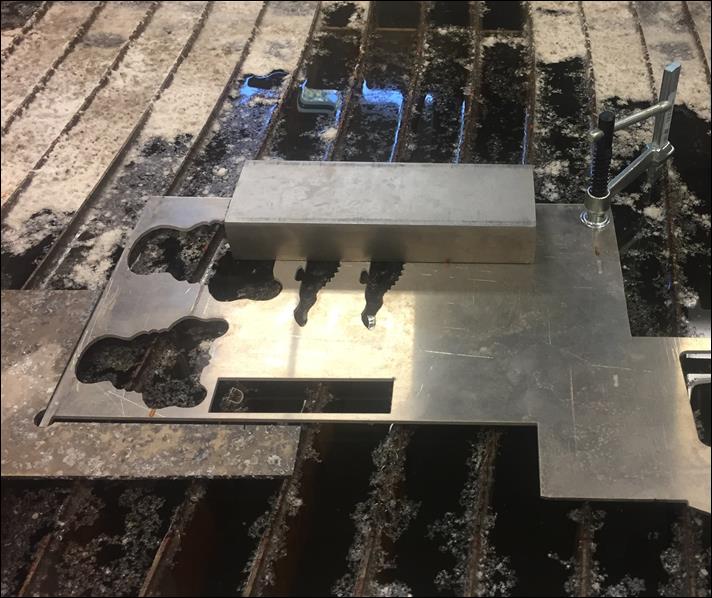
3.
The weight of
the part is usually NOT enough to prevent movement, so use F-clamps, but make sure they are positioned with enough clearance so
the AWJ cutting head will not collide with them when cutting.
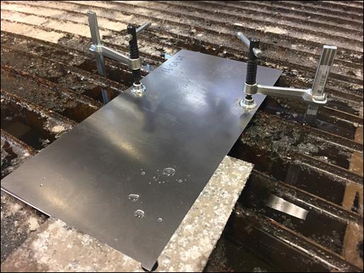
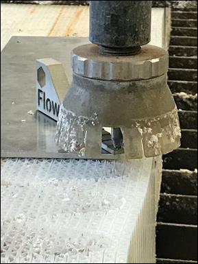
4.
Water jet brick (polypropylene honeycomb sheeting, aka Coroplast) can be used for supporting small or thin parts
which cannot be easily tabbed or supported to prevent falling into the
tank. Only use water jet brick when
necessary, as it’s expensive and using it makes a mess in the tank because the
plastic floats on top of the water.
5.
When finished and unloading the part, wipe off the F-clamps
so they don’t rust while being stored wet.
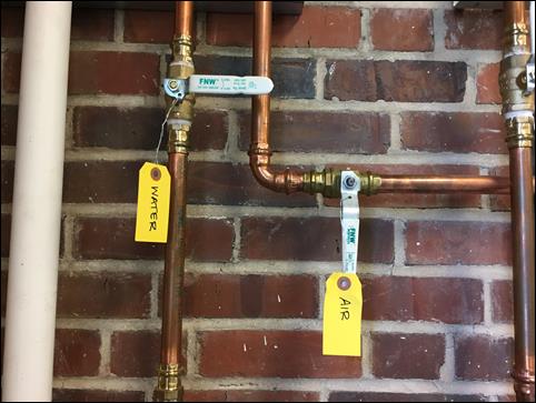
Machine Start-Up [RETURN TO TOP]
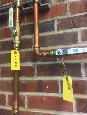
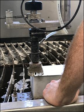
1.
Turn ON labeled water and air valves located in NW corner of
the room (valves shown below in ON position).
2.
Turn ON main machine power switch on the back side of the
machine. This causes the PC on the front
of the machine to boot as well.
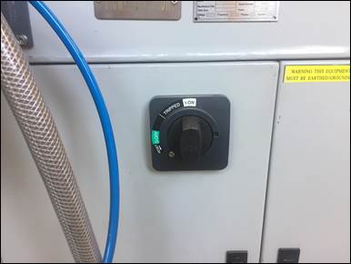
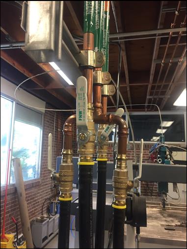
3.
Ensure the four valves above the pump are rotated to ON
position (the Sanitary Drain valve is throttled back to 45°). These valves
should already be ON but always visually double check.
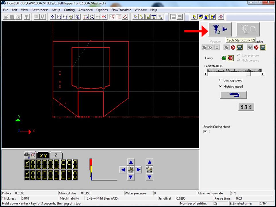
Cutting the Part using FlowCUT [RETURN TO TOP]
1.
Open FlowCUT
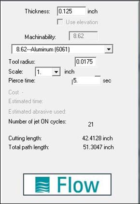
2.
Open the FlowPATH .ORD file
you wish to cut
a.
Specify the material properties
i.
Thickness
ii.
Material type
iii.
Tool radius should be already set to 0.0175” (half the
mixing tube diameter)
iv.
Scale should be 1 unless you purposely want to change it
v.
Pierce will update automatically (do not change)
b.
Use Preview
(bottom menu) to view simulated paths
c.
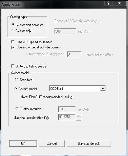
Click Run Machine
when ready to cut
i.
Click OK when
Apply Model screen pops up (use default settings)
3.
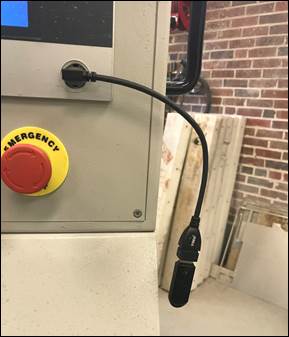
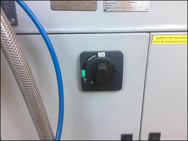
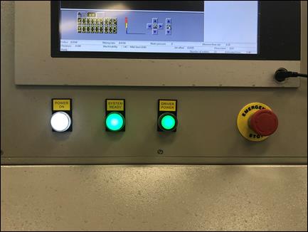
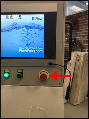
Homing Machine
a.
Rotate E-stop knob
on controller and push Drive Power
button to energize the servos
i.
All three lights should be illuminated and you should hear
the buzz of the motors
b.
Select the home icon
on the bottom right and select Yes to home the Z-axis
![]()
c.
Select the other home
icon to home the X & Y-axes
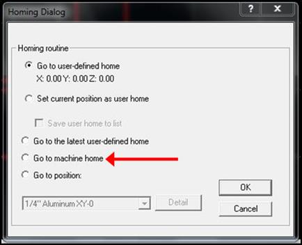
i.
In the Homing Dialog screen, select Go to machine home and hit OK
ii.
Be cautious and stay clear of the moving arm above
the tank
4.
Load Material
a.
Carefully place stock on table and secure using clamps and
weights (refer to Part Loading & Clamping
section for more details)
5.
Homing Part
a.
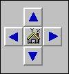
Hand jog the jet using the key pad arrows for X and Y axes and the page up/down keys for the z axis
b.
The X and Y axes are eyeballed by splitting the nozzle down
the middle similar to checking the zero with the edge finder on the milling
machine
i.
You can jog the machine down the length of the stock to
verify
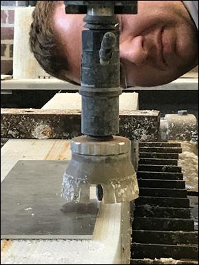
c.
The jet nozzle should be ~ 0.1” above the part for the Z axis
i.
Use the smallest step on the FLOW step gauge found on top of
the controller to verify height is set properly.
ii.
Approach the final Z height slowly and ALWAYS move the step gauge out of the way before bumping the Z
closer. Running the fragile carbide mixing tube into
the step gage or workpiece will destroy it.
d.
When you are positioned correctly for home, click the X,Y-axes home icon again
e.
Click Set current
position as user home (similar to setting a G54 work offset on the CNC) and
click OK
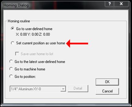
i.
If this is done correctly, a red dot should appear at the
corner the workspace
f.
If you hand jog away from your new home position before
starting the program, the machine will throw a warning: Do you want to set the
current jet position as new Home Position?
i.
Click No,
otherwise the current position will be the new Home
6.
Starting Machine
a.
Double check your set-up: the bottom of the screen will list
your selected material, and material thickness
b.
Verify that Water
and Abrasive in the right menu are
set to Auto and Feedrate is 100% (or
lower if you are cautious)
c.
When ready, click the green
light icon next to Pump to activate
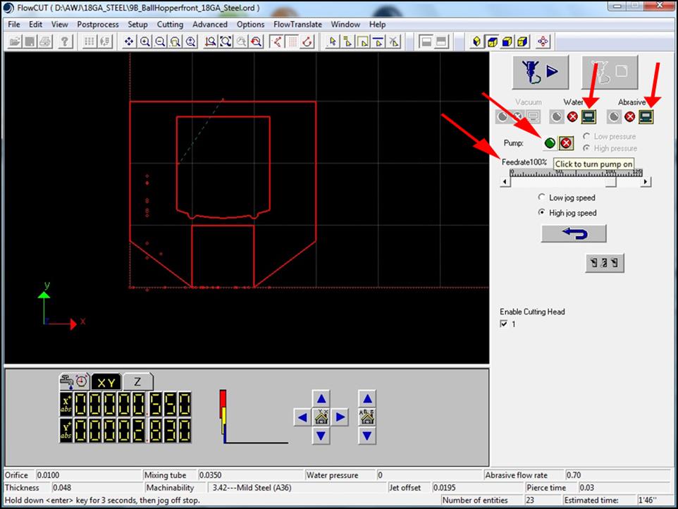
d.
Once full pressure has been reached on the large gage above
the AWJ pump, click Cycle Start
(Play button with nozzle image)
e.
Machine does
not feed hold!
i.
If you need to stop the program hit ESC key or if it’s an emergency, use any of the E-STOP buttons
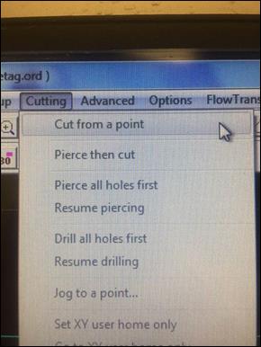
ii.
If you stop in the middle of a program, you can continue by
selecting Cutting → Cut From Point → (choose a point
near/before where you ended the program)
7.
After program finishes, click OK to clear the note stating that the program is finished (the pump will make a LOUD noise upon shutdown)
a.
Home Z-axis or jog up to clear any obstruction
b.
Hand jog nozzle away from part so you can unload finished
parts (edges will be sharp and need deburring)
8.
Shutdown Procedures
a.
Home Z-axis in FlowCUT and wait
until full retraction occurs to provide maximum clearance upon restarting
machine
b.
After returning home,
push E-Stop on controller to
deactivate servos
c.
Close FlowCUT and FlowPATH programs
d.
Run through the typical Windows Shutdown
i.
Start Menu → Shutdown
ii.
Wait until fully off (black screen) before proceeding
e.
Turn the black power switch on the backside of the machine
to OFF (the abrasive hopper will make a LOUD noise)
f.
CLOSE incoming air and water valves, leave the pump valves
ON
g.
Rinse parts with water hose (mounted on wall) and turn OFF
its shutoff valve
h.
Remove material from the top of the tank and discard or
return to material rack
Important Notes [RETURN TO TOP]
1. Always wear safety glasses and ear protection when operating the
machine.
2. Always CLAMP YOUR MATERIAL SECURELY before running the program;
the buoyancy force produced by the water is quite large and can shift any parts
not clamped securely, destroying the part and possibly damaging the cutting
head.
3. The
splash zone around the machine is approximately 3ft; remove any items that
could potentially be damaged.
4. The
red dot trail showing that path of the cutting jet can be cleared by pressing F12.
5. It’s
possible to restart a cutting path at any point along the programmed path by
selecting Cutting → Cut From Point.
6. Be careful when jogging the machine, as the carbide mixing tubes are
very brittle and easily broken if bumped into anything rigid.
7. Be careful all geometry in your imported .dxf
or .dwg file is on ONE PLANE, as negative Z-moves
will plunge the mixing tube into the workpiece.
8. When servicing the machine ALWAYS position the AWJ nozzle over a
large sheet of material so you don’t accidentally drop parts into the tank
while (dis)assembling, as once you drop them, it’s too late to do anything
about it.
1.
Understand the limitations
of water jet cutting:
a.
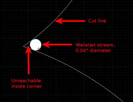
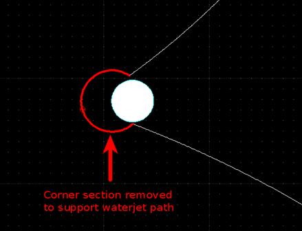
Kerf width
(cutting jet diameter). The cutting jet
radius is typically 0.0175 – 0.020″, so if you need features that are
sharper than that, design
for a relief cut, or plan on a secondary operation.
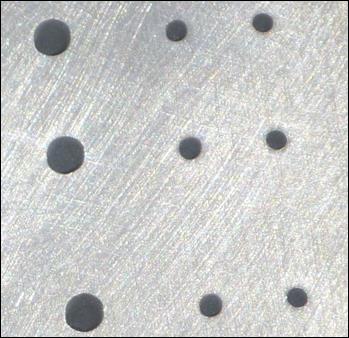
b.
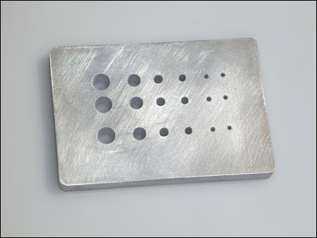
Minimum hole size. Keep holes > 0.1″ due to piercing
migration.
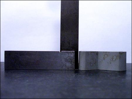
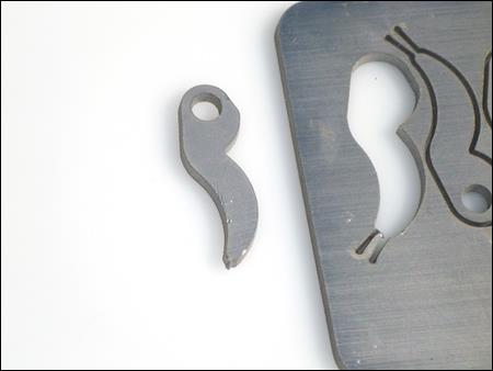
c.
Taper. Metals will taper
outward from the top face when cut on the water jet (as seen in the figure
below). With plastics, it is the
reverse: plastics will taper inward from the top face when cut on the water
jet.
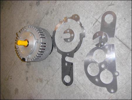
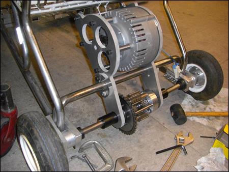
2.
Motor Mounts
and Bearing Blocks. Here
are some interesting ideas.
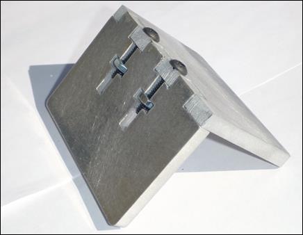
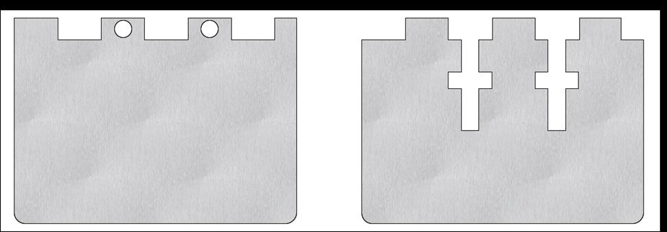
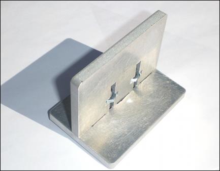
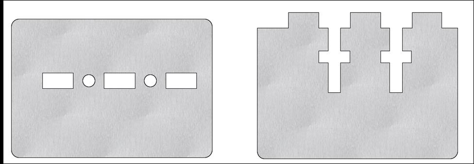
3.
Tab and Slot
with T-Nut Construction. Here’s
a crafty design for angled brackets that bolt together without secondary
operations.
4.
Tabbing. Tabbing is the
action of connecting small parts to each other or to the sheet of material to
prevent them from falling into the water jet tank when they are cut. Of even higher risk is the chance of a small part flipping
upwards and protruding into the traverse path of the cutting nozzle, causing a
collision and destroying brittle mixing tube. So use tabs generously (they are easily added
to the part during pathing using FlowPATH).
5.
Cutting Fonts and signs.
6.
Reducing Costs. Since AWJ cutting prices are based on setup
time, material cost, and machining time, anything you can do to reduce
these will reduce in cheaper part cost.
a.
Follow the tips for good AWJ drawing practices in the DML
AWJ Design Guide:
i.
Make proper drawings with closed geometric paths and no
redundant geometry.
ii.
Draw parts true scale.
iii.
Include only the part features you want cut in the file, as
well as one reference dimension to verify scaling.
b. Sharp inside corners and tight arcs take longer to cut drive up part cost. The sharper the corner and tighter the arc, more the machine has to slow down.
c.
Follow basic DFM practice of making the parts out of the
most machineable material possible. You can also reference OMAX’s Engineer’s
Guide for Designing AWJ Parts