This webpage
outlines the knowledge necessary to safely program, set up, and run the CNC
machines in the Design & Manufacturing Laboratory. Many of the images and links are authored by others
and hyperlinked accordingly.
Table
of Contents
Machine Manuals & Reference Documentation
Part CAD Model [RETURN TO T.O.C.]
We typically
begin with an accurate CAD model of
the part we wish to make. Once the part
model is checked for accuracy, a good
quality drawing must be made of the part that includes appropriate tolerances for each part feature, as well as notes
about which surfaces need finishing,
and how good the finishes must be. A
printed copy of this drawing will be used both for part programming and
post-machining inspection, so take the
necessary time to make an accurate and easily readable drawing. If you can’t do this, you certainly don’t
have the skills, patience, or time to attempt part manufacturing.
For most
parts manufactured on the CNC milling machines, the part model is directly
imported into the CAM software, which in turn is used to generate the toolpaths
used to cut the part.
For most
parts manufactured on the CNC lathe, the toolpaths are programmed manually,
because the slightest misunderstanding of the code generated using CAM software
can be catastrophic to the user, machine, and cutting tool. When creating a part drawing used to program
the CNC lathe, all part diameters must be dimensioned, as well as the starting
and ending coordinates for all arcs/radii.
In addition, all Z-axis coordinates should be dimensioned from the face
of the part.

Example of conversational programming on
the CNC lathe
Part
Setup Sheet [RETURN TO T.O.C.]
In addition to an accurate and clear detail drawing, you must also
complete a setup sheet for the machine you plan to use to manufacture your
part:
The setup sheet includes details of each tool used in the manufacturing,
as well as sketches and notes explaining where your part datums/zeros are
located for each operation. Worded
another way, the setup sheet should
contain ALL information necessary for another competent operator to
successfully setup and run your part program. Poorly completed setup sheets typically
result in a poorly completed parts.

Setup sheet details for CNC milling
machine
Here are
a few interesting comments about The Art of the Setup Sheet
Part
Programming [RETURN TO T.O.C.]
There are
three ways to program CNC machines: CAM (computer aided manufacturing),
conversational (subroutine library), or directly hand writing G&M
code. We primarily use two methods in
our lab: CAM for programming the CNC mills and direct hand coding for programming
the CNC lathe.
Like CAD software, there is, and will likely always be, a variety of CAM
softwares on the market for use generating toolpaths for CNC milling
machines. Some of the more popular CAM
softwares used in our laboratory include MasterCAM, SolidCAM, Fusion360,
and HSMWorks, the
latter two being free for any university student at the time this document was
authored.


Each of these CAM packages comes with an assortment of tutorials and
there are also plenty on YouTube, so I will not cover CAM use in this document.
Tool Selection [Printed
Version] [RETURN TO T.O.C.]
General guidelines for selecting appropriate cutting tools when milling:
1. Select the cheapest tool
that will do the job. HSS (high
speed steel) tools are approximately 2.5X cheaper than WC (tungsten carbide)
tools.

2. Select the toughest tool
that will do the job. HSS tools
are much tougher (resistant to impact without chipping) than WC. Since HSS tools are also much cheaper, it’s a
proverbial win-win when machining nonferrous materials like aluminum.

3. Select the
largest/strongest tool that will do the job.
A ¼″ endmill is a lot stronger than an 1/8″ endmill, so
unless absolutely necessary, try to select the largest tool that will do the
job. The law of diminishing returns
applies here, as once endmills reach ½″ in diameter, they are typically
strong enough to cut anything we need to, and at that point larger tools just
cost more money without much gain in strength / stiffness. Execution of this point often requires
reevaluating the design to determine why a larger feature radius cannot be used
to accommodate a larger cutting tool.

4. Select the shortest tool
that will do the job. Almost every
cutting tool used on a milling machine is essentially a cantilevered beam whose
stiffness is inversely proportional to the cube of the length sticking out of
the collet. So always select the
smallest L:D (length-to-diameter) ratio possible for increased productivity,
tool life, and surface finish.
5. Select the appropriate
number of flutes for the job. Fewer flutes
improve chip evacuation and more flutes improve tool stiffness and productivity
(since more chips can be cut per each tool rotation). Do not use more than 3 flutes when full
slotting in non-ferrous materials like aluminum.

6. Use roughing tools for
roughing and save finishing tools for finishing. Roughing tools are much stronger than
finishing tools because they have generous fillets or chamfers on their cutting
tips and serrated edges to break up chips into smaller pieces for improved
evacuation and less chance of re-cutting.
Using one tool to rough and finish wears it out much quicker, and often
chips it before it even gets to the finish passes. So using roughing tools whenever possible
actually reduces the total tooling cost for the job.

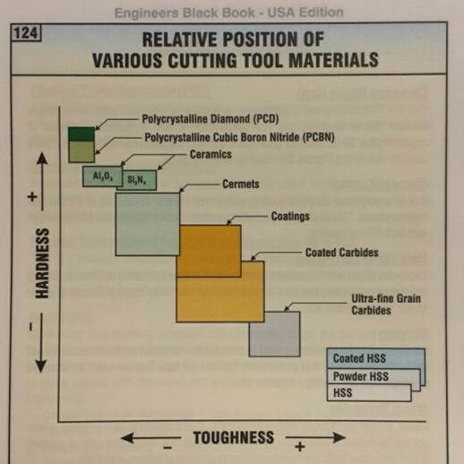
7. Understand the benefits of
WC (tungsten carbide) tools (aka the 2.5 rules). If you spend any time in the shop you will
see tools made of WC, which in layman’s terms has similar material properties
to ceramics. WC tools can withstand
approximately 2.5X more heat than HSS tool alloys (or more in the right
application!). Coincidentally, WC is
also about 2.5X stiffer than steel, which means it will deflect significantly
less during heavy cutting. The downsides
(as previously mentioned), are that WC is approximately 2.5X more expensive and
much more brittle (less tough) than HSS, which is why both tool materials
remain popular in modern manufacturing.
8. HSS or WC for finishing? Because WC is made from a bunch of
micro-grain powders, the cutting edge can only be ground so sharp. HSS can be honed to a sharper edge, but like
an uber-sharp knife, it won’t hold that sharper edge as long. So when trying to obtain the best surface
finish possible cutting aluminum, HSS finish tools can actually work better,
but they won’t stay sharp as long.
However, please do not interpret this point as saying you can’t get a
very nice finish with carbide in aluminum, because you most certainly can.
9. Use the right tool coating
for the job (or none at all). The only
tool coatings that work well when cutting aluminum are ZrN (zirconium nitride)
or TiB2 (titanium diboride).
TiN (titanium nitride), TiAlN (titanium aluminum nitride), TiCN
(titanium carbo nitride) are intended for cutting ferrous metals and tend to
gall when cutting aluminum.
Harvey
Tool’s Excellent Tool Coatings Chart
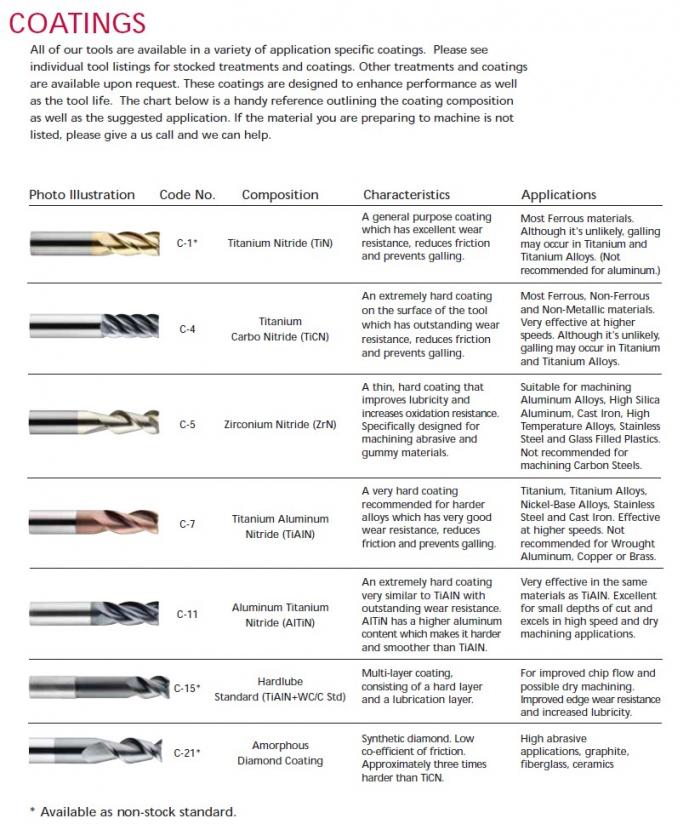
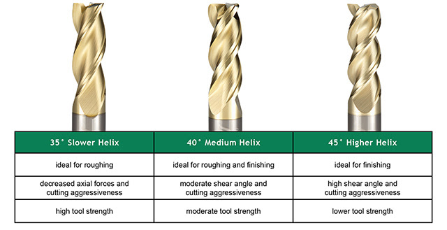
10. Select the proper helix
angle. Shallower helix angles provide
stronger cutter edges for hardened materials, decreased axial forces and
cutting aggressiveness, less potential for tool pull-out, less flute engagement
and therefore less potential for chatter.
Higher helix angles provide a greater shearing action and therefore
lower power requirements, increased axial forces and cutting aggressiveness,
higher potential for tool pull-out, and more flute engagement and therefore more potential for chatter.
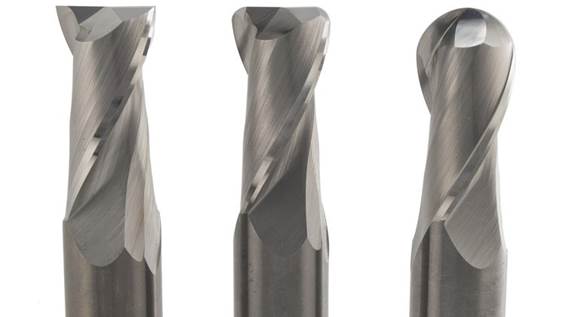
11. Understand commonly
available endmill geometries. Endmills are
available with flat ends (the most common), ball ends, and convex radii in
place of the normally sharp corners.
Endmills are also available with concave corner radii for cutting
fillets onto external corners.
12. Use multiple tools when
cutting deep features. A standard
length endmill may have flutes that measure 2×D in length, where D is the tool
diameter. For example, a standard ½″
endmill may have 1″ of useable
flute length. If cutting a feature that
requires a longer endmill, always use a normal length tool first and only then
switch to the longer tool(s) as necessary, since using the longer tool for the
first inch of cutting depth would break Rule #4 above. In cases where the finish is important,
longer endmills are also available with radially relieved shanks so they don’t
gall the portion of the part previously cut.
13. A few cautions!
a.
Not
all endmills are center-cutting, meaning not all can be used to plunge mill (like a
drill bit).
b.
Endmills
do not like to plunge, as they have serious trouble with chip evacuation,
which leads to chip recutting, and damaged cutting edges. Predrill a hole before plunging (always
preferred and easiest on the tool) or ramp into the part using combined radial
and axial displacement.
c.
Damaged
tools are still quite useful in forgiving materials, but not in tough
materials. Using a dull, damaged cutter in
easy to machine materials like aluminum will simply result in a poor finish,
which can be remedied by performing a finish pass with a nicer tool. So don’t be so quick to grab the newest tool
in the cabinet each time you have a part to make, especially if there’s a lot
of roughing to be performed. In
addition, be encouraged to use worn or damaged tools to explore the limits of
what they can do. BUT … do not try that
with tougher to machine materials like stainless or titanium, as dull or
damaged tools used in these materials will catastrophically overheat and fail
before you have time to react (due to strain hardening of the material being cut).
d.
Feeding
an endmill too slowly is as bad for it as feeding it too quickly. When the chip thickness becomes too small,
each cutting edge is smearing rather than cutting, which produces significantly
more heat and quickly dulls the cutting edge.
The general rule of thumb is to not feed an endmill slower than 25% of
its recommended feed per tooth. So if
the suggested chip load for a ½″ endmill is 0.004″/tooth, bad
things will start happening when you drop the feedrate lower than about 0.001″/tooth.
e.
Cutter
deeper produces proportionally higher axial forces. The tangential cutting force on the endmill’s
helical cutting edge is equal to the cutting stiffness of the material times
the chip thickness times the depth of cut.
If you cut twice as deep, the forces are twice as large. This means you must be more careful to ensure
the part is clamped securely when taking deeper axial cuts with the side of an
endmill, even if only removing a small
amount of material.
Tool Selection for CNC Turning [RETURN TO T.O.C.]
General guidelines for selecting appropriate cutting tools when turning:
1. Understand selecting tools
for CNC turning is inherently more complex than selecting tools for CNC milling because
milling basically uses two types of tools: endmills and drills. Facemills, fillet tools, reamers, and taps
all fall into these two categories. But
when it comes to CNC turning, there is a myriad of different types of tools:
facing, turning, profiling, grooving (OD or face), drilling, grooving, parting,
knurling, etcetera. The following images
are taken from the Engineers
Black Book, a truly exceptional resource on the topic of cutting tool
identification and selection.
2. Select the cheapest tool
that will do the job. Select the best tool you
can afford that will do the job. A lot more time goes into setting up a CNC
lathe than a CNC mill, so shift your mind from always selecting the cheapest
tool to selecting the best tool you can afford that will do the job. Yes, HSS tools are approximately 2.5X cheaper
than WC tools, and they work great when cutting non-ferrous materials, but we
often find ourselves making parts out of alloy steels and aerospace alloys that
would force us to run the parts at 25-40% of the speed that comparable geometry
WC would allow. For this reason, a LOT
of indexable tooling (steel toolholders with replacement WC inserts) is used on
CNC turning centers.
3. Select the toughest tool
that will do the job. You already
know HSS tools are much tougher (resistant to impact without chipping) than
WC. However, WC tools are available in a
spectrum of toughness vs. hardness combinations that target applications
requiring higher toughness or higher wear resistance.
4. Select the
largest/strongest tool that will do the job.
A ¼″ endmill is a lot stronger than an 1/8″ endmill, so
unless absolutely necessary, try to select the largest tool that will do the
job. The law of diminishing returns
applies here, as once endmills reach ½″ in diameter, they are typically
strong enough to cut anything we need to, and at that point larger tools just
cost more money without much gain in strength / stiffness. Execution of this point often requires
reevaluating the design to determine why a larger feature radius cannot be used
to accommodate a larger cutting tool.
5. Select the shortest tool
that will do the job. Almost every
cutting tool used on a milling machine is essentially a cantilevered beam whose
stiffness is inversely proportional to the cube of the length sticking out of
the collet. So always select the
smallest L:D (length-to-diameter) ratio possible for increased productivity,
tool life, and surface finish.
6. Use roughing tools for
roughing and save finishing tools for finishing. Roughing tools are much stronger than
finishing tools because they have generous fillets or chamfers on their cutting
tips and serrated edges to break up chips into smaller pieces for improved
evacuation and less chance of re-cutting.
Using one tool to rough and finish wears it out much quicker, and often
chips it before it even gets to the finish passes. So using roughing tools whenever possible
actually reduces the total tooling cost for the job.
7. Use the right tool coating
for the job (or none at all). The only
tool coatings that work well when cutting aluminum are ZrN (zirconium nitride)
or TiB2 (titanium diboride).
TiN (titanium nitride), TiAlN (titanium aluminum nitride), TiCN (titanium
carbo nitride) are intended for cutting ferrous metals and tend to gall when
cutting aluminum.
8. A few cautions!
a.
Not
all endmills are center-cutting, meaning not all can be used to plunge mill (like a
drill bit).
b.
Endmills
do not like to plunge
c.
Damaged
tools are still quite useful in forgiving materials, but not in tough
materials.
d.
Feeding
an endmill too slowly is as bad for it as feeling it too quickly.
e.
Cutter
deeper produces proportionally higher axial forces.
We will divide tool setup into two categories: setup for milling and
setup for turning.
Setting up tools for
milling:
1. Read and follow the Tool Selection guidelines posted previously so you
know exactly what type of tool you need (size, material, type (rougher,
finisher, flat, ball, radius, etc.), and length of cut). Do not move onto the next step until you
understand exactly what you need or you have specific questions.
2. If you do not own the
tools you a tool is not already loaded in the machine, bring your setup sheet to Mike and ask for it. Do not open the tooling cabinets (to see
what’s available for use or to remove a tool) without first asking Mike’s
permission, as most of the tools belong to DML and the rest are under Mike’s
supervision so they last for more than one use.
If you ask Mike for a tool he
feels you are qualified to use, he will allow you to use it, as long as you
replace it if you break it.
3. NEVER touch the tapered
portion of a toolholder, as doing so causes corrosion that permanently
degrades its precision.
4. Clean each toolholder
before each use. Always wipe
off the taper with a clean rag, remove any corrosion from the taper using a
piece of Scotch-Brite, spray a light coating of WD-40 on the freshly cleaned
taper, and place a small dab of grease on the pull stud bulb. If
you have questions about how to clean a toolholder, ask, as loading a dirty or
corroded toolholder will damage the spindle taper.
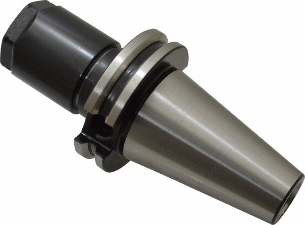
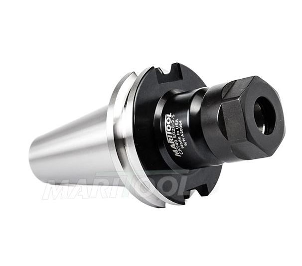
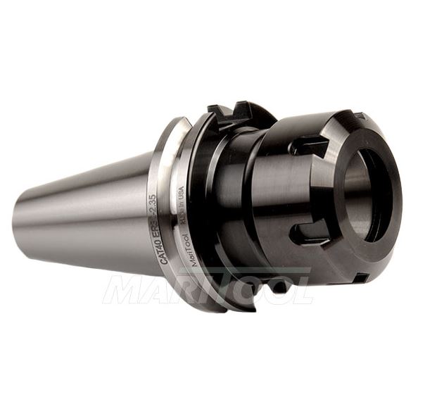
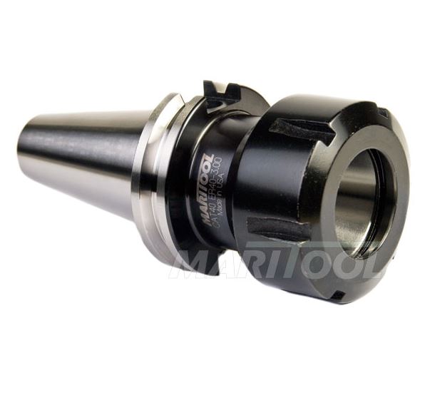
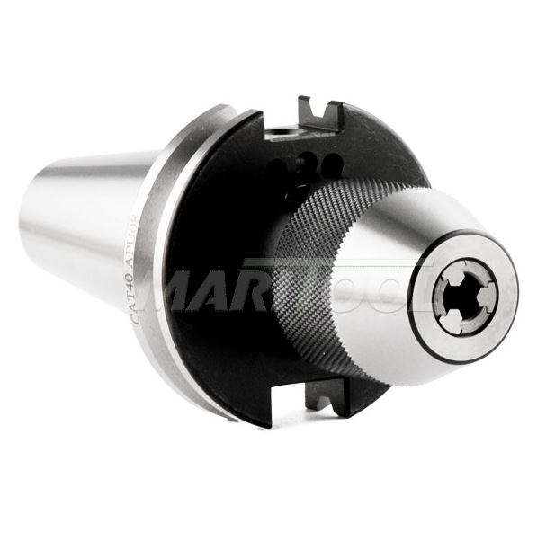
5. Select the appropriate
type of toolholder. Smaller
series toolholders have smaller nut diameters which allow additional clearance
when reaching into tighter places.
However, smaller series toolholders offer less clamping torque on the
tool to resist pulling it out of the holder when used aggressively. The following table lists the type of
toolholders we currently have in lab, the min and max size tool shanks each
type will clamp, and the relative clamping strengths.
|
Toolholder Style |
Min
Clamping Diameter |
Max
Clamping Diameter |
Nut
Diameter |
Nut
Torque (lb-ft) |
Relative
Clamping Strength (1 – 10) |
|
1/16″ |
3/8″ |
0.85″ |
20 |
2 |
|
|
1/16″ |
3/4″ |
1.5″ |
60 |
3 |
|
|
1/16″ |
3/8″ |
1.1″ |
30 |
3 |
|
|
3/32″ |
1/2″ |
1.35″ |
60 |
4 |
|
|
5/32″ |
3/4″ |
2″ |
100 |
6 |
|
|
9/32″ |
1″ |
2.5″ |
130 |
8 |
|
|
1/8″ |
1″ |
0.8″ – 2″ |
snug J |
||
|
- |
- |
- |
- |
- |
- |
|
0.02″ |
5/16″ |
1.5″ |
N/A |
5 |
|
|
0.02″ |
1/2″ |
2″ |
N/A |
5 |
|
6. Select the shortest
toolholder. When selecting the toolholder,
always choose the shortest projection length that allows adequate tool
clearance for the deepest depth cut and adequate nose clearance for anything
with which it could collide (a part wall, vise jaw, clamping fixture,
etc.). Worded another way: always select the stiffest toolholder
available that provides adequate working clearance.
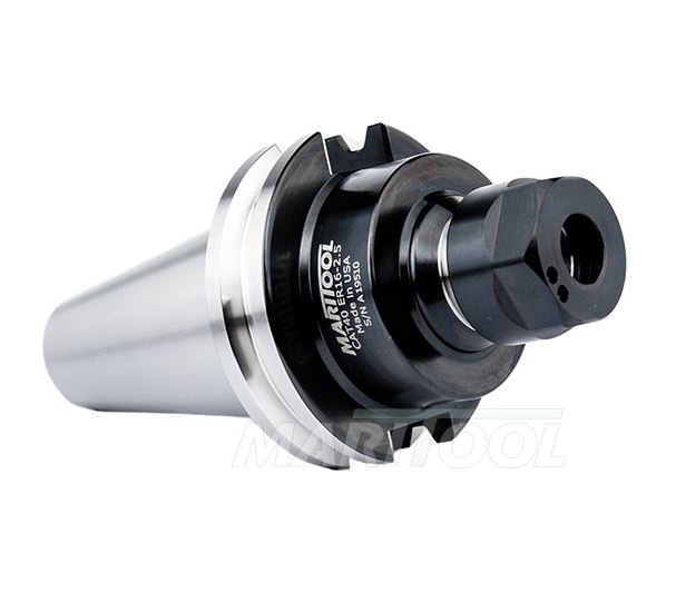
7. When installing tools in
ER-style collet chucks, always load the
collet into the collet nut BEFORE installing the collet nut onto the collet
chuck or you will destroy the collet, nut, and toolholder.
8. Properly torque collet
nuts. Collet chuck nuts should always
be torqued to the value specified in the above table when using any tools larger
than 1/8” (because small tools will likely break before they pull out of a
collet chuck).
9. When installing a
toolholder into the CNC, always rotate the spindle so the toolholder engagement
tangs are closest to the operator and visually check that
they engage their mating slots in each toolholder BEFORE releasing the
toolholder clamping button. In addition,
be VERY CAREFUL when inserting a toolholder into the spindle TO NOT slam the
pull stud into the side of the precision ground taper.
10. Probe each tool length
IMMEDIATELY after loading, as forgetting
to do so can result in extensive tool and machine damage. If you don’t have
time to probe a tool, don’t load it, as the consequence can be disastrous.
11. Put tools away when done. When you are finished with your part, unload
any tools you loaded, returning the tools to their appropriate plastic
containers and to Mike for storage, and return toolholders and collets to their
respective carts. Failure to do so will
result in suspension of CNC use privileges, because it’s disrespectful and
that’s how tools are lost.
Setting up tools for
turning:

1. Read and follow the Tool Selection guidelines posted previously so you
know exactly what type of tool you need (size, material, type, and
length of cut). Do not move onto the
next step until you understand exactly what you need or you have specific questions.
2. If you do not own the
tools you a tool is not already loaded in the machine, bring your setup sheet to Mike and ask for it. Do not open the tooling drawers (to see
what’s available for use or to remove a tool) without first asking Mike’s
permission, as most of the tools belong to DML and the rest are under Mike’s
supervision so they last for more than one use.
If you ask Mike for a tool he
feels you are qualified to use, he will allow you to use it, as long as you
replace it if you break it.
3. Clean each toolholder
block before each use. Always wipe
off the precision flat mating surface and remove any corrosion using a piece of
Scotch-Brite, a 400 grit stone, and a clean rag. If
you have questions about how to clean a toolholder block, ask, as loading a
dirty or corroded toolholder will damage the turret contact surface.
4. Select the appropriate
type of toolholder. Smaller
series toolholders have smaller nut diameters which allow additional clearance
when reaching into tighter places.
However, smaller series toolholders offer less clamping torque on the
tool to resist pulling it out of the holder when used aggressively. The following table lists the type of
toolholders we currently have in lab, the min and max size tool shanks each
type will clamp, and the relative clamping strengths.
|
TURNING TOOLHOLDER SELECTION |
|||||
|
Toolholder Style |
Insert
Style |
Max
Clamping Diameter |
Nut
Diameter |
Nut
Torque (lb-ft) |
Relative
Clamping Strength (1 – 10) |
|
CNMG |
CNMG |
3/8″ |
0.85″ |
20 |
2 |
|
DNMG |
DNMG |
3/4″ |
1.5″ |
60 |
3 |
|
VNMG |
VNMG |
3/8″ |
1.1″ |
30 |
3 |
|
PARTING |
|
|
|
|
|
|
|
|
|
|
|
|
|
|
|
|
|
|
|
|
|
|
|
|
|
|
|
|
|
|
|
|
|
|
|
|
|
|
|
|
|
|
|
|
|
|
|
|
3/32″ |
1/2″ |
1.35″ |
60 |
4 |
|
|
5/32″ |
3/4″ |
2″ |
100 |
6 |
|
|
9/32″ |
1″ |
2.5″ |
130 |
8 |
|
|
1/8″ |
1″ |
0.8″ – 2″ |
snug J |
||
|
- |
- |
- |
- |
- |
- |
|
0.02″ |
5/16″ |
1.5″ |
N/A |
5 |
|
|
0.02″ |
1/2″ |
2″ |
N/A |
5 |
|
5. Select the shortest
toolholder. When selecting the toolholder, always
choose the shortest projection length that allows adequate tool clearance for
the deepest depth cut and adequate nose clearance for anything with which it
could collide (a part wall, vise jaw, clamping fixture, etc.). Worded another way: always select the stiffest toolholder available that provides adequate
working clearance.
6. When installing tools in
ER-style collet chucks, always load the
collet into the collet nut BEFORE installing the collet nut onto the collet
chuck or you will destroy the collet, nut, and toolholder.
7. Properly torque collet
nuts. Collet chuck nuts should always
be torqued to the value specified in the above table when using any tools
larger than 1/8” (because small tools will likely break before they pull out of
a collet chuck).
8. Probe each tool length
IMMEDIATELY after loading, as forgetting
to do so can result in extensive tool and machine damage. If you don’t have
time to probe a tool, don’t load it, as the consequence can be
disastrous.
9. Put tools away when done. When you are finished with your part, unload
any tools you loaded, returning the tools to their appropriate plastic
containers and to Mike for storage, and return toolholders and collets to their
respective carts. Failure to do so will
result in suspension of CNC use privileges, because it’s disrespectful and
that’s how tools are lost.
Programming
Tips [RETURN TO T.O.C.]
1. Follow the tool selection
tips above. Seriously: read and follow them.
2. Calculate speeds and feeds
using the
information presented in EML2322L. If you don’t understand how your feeds and speeds are
calculated, DO NOT continue. “I
just used what someone else gave me” is NEVER an acceptable justification for
breaking a tool or yanking a part out of the vise because you didn’t understand
what you were doing. The linked document
is easy to understand and after reading it thoroughly, you can ask Mike as many
questions as you like.
3. Predrill whenever
possible. Endmills do not like to plunge
because that’s when the cutting tips are most likely to chip, ruining the
tool. Pre-drilling is best, followed by
helical ramping.
4. Understand Ft =
Ks × b × h, where
Ft is the tangential cutting force
Ks is the material cutting stiffness
b is the depth of cut
h is the maximum chipload
Therefore
cutting forces are proportional to depth of cut, and newer “high efficiency” /
“high speed” programming methods place large axial forces on the cutting tool
(trying to pull it out of the toolholder) and workpiece (trying to pull it out
of the vise or other workholding).
5. Cut deeper pockets using
multiple tools. Cutting
deeper than 2 tool diameters requires the use of longer flute tools. It’s natural to want to just cut the entire
pocket using these longer tools.
Don’t. Use the regular length (typically
2XD flute length) to begin the pocket and switch to sequentially longer tools
(3XD and beyond) to finish the pocket.
Using the longest tool for the entire pocket dramatically reduces the
metal removal rate because of the large reductions in spindle speed and
feedrate required to not destroy the endmill.
6. Program reamers properly. Reamers should be run at half
the spindle speed and twice the feedrate of the comparable size drill bit. They should also be retracted with the
spindle off to preserve the finish and mitigate bell-mouthing of the hole
entrance.
7. Long tools do not like
high speeds. Longer tools need their spindle
speeds decreased by as much as 75% to reduce vibration to prevent premature
tool failure. A rule of thumb that works well is to reduce the calculated spindle
speed by 25% for every tool diameter D over 2XD cutting depth and only increase
your spindle speed after verifying adequate cutting tool stiffness and chip
evacuation.
8. Read the Helical
CNC Milling Guidebook. This
relatively short document contains a wealth of information with excellent
illustrations.
1. Load the part
using the most robust workholding available.
If clamping in the vise, use the long steel handle, not the short
aluminum toy, as the higher cutting forces in the CNC mill will yank a lightly
clamped part right out of the vise and send it through a window like a rotating
helicopter blade. If the part is fragile
(like a highly pocketed Turner’s cube) use a torque wrench for consistent
clamping force
2. Use the
electronic workpiece probe to set ALL THREE part zeros.
Program Dry (aka
Test) Run [RETURN TO T.O.C.]
1. Understand a
replacement VF-2 costs about $80k.
Remember this value because that’s how much it can cost to fix a serious
mistake if you don’t pay attention to the rest of this document.
2. When ready to
test the program, offset the Z-axis height value stored in the relevant work
offset machine register by an inch or more (if your program cuts deeper than an
inch) in the POSITIVE Z direction; write down this offset value.
3. Jog the Z-axis
so the tool is at least 6 inches above the part (less as you gain experience).
4. Set the RAPID
override to 5% or 25% (which is still very fast on the VF-2, so be careful).
5. Open the
program in the machine editor, press the RESET button, and go into MEM mode.
6. With your left
thumb on the green CYCLE START button and your right thumb on the red FEED HOLD
button, begin the program by pressing CYCLE START and pause the program by
pressing the FEED HOLD BUTTON.
7. Adjust the
RAPID button as necessary to ensure the tool doesn’t rapidly move into the
part.
8. Run enough of
the program to ensure the part zero and scaling are correct.
9. When ready to
run the program, offset the Z-axis height value stored in the relevant work
offset machine register by the SAME VALUE previously entered in STEP 2 above (and
written down), only in the NEGATIVE Z direction.
Prototype
(First Part) Run [RETURN TO T.O.C.]
1. Jog the Z-axis
so the tool is at least 6 inches above the part (less as you gain experience).
2. Set the RAPID
override to 5% or 25% (which is still very fast on the VF-2, so be careful).
3. Set the
SPINDLE SPEED to 60% and the FEEDRATE to 40% overrides.
4. Run the first
tool, being very cautious to FEED HOLD if anything LOOKS, SOUNDS, FEELS, or
SMELLS wrong!
5. If everything
seems fine, then you can monitor the spindle speed and chipload on the CURRENT
COMMANDS screen, and slowly bring the overrides up to 100%.
6. When a tool change
occurs, be careful not to douse all the tools with coolant (you may have to
manually turn off the COOLANT on the control panel after FEED HOLDING).
7. Reset the
SPINDLE SPEED (60%) and FEEDRATE (40%) overrides for each new tool used in your
program and repeat steps 4 thru 6.
Production Run [RETURN TO T.O.C.]
1. If ANYTHING is changed in the program, you must
re-prove the associated portion(s) of the program and tool(s) involved.
2. If you don’t CRITICALLY measure EVERY important
feature on your last part, you will quickly generate a lot of scrap parts. Because of human error, it’s always good
practice to ask another person whose metrology skills you trust to use the
accurate and clear detailed drawing you created previously to check each
important feature on your last part.
3. Understand tools wear, so it’s necessary to
inspect parts as they come off the machine during production runs.
Important
Points [RETURN TO T.O.C.]
1. NEVER run the CNC while
talking to or with another person. FEED HOLD,
carry on your conversation, instruct them to be quiet if you are okay with them
watching, and then continue setting up tools, probing the workpiece, proofing
the program, or running the part.
2. Never press the ENTER
button on the controller without knowing what you are doing. If you mistakenly do so while editing a program,
that data will overwrite whatever line is highlighted in the program, including
the custom probing macro programs, which are virtually impossible to
troubleshoot due to their complexity.
3. Do not leave the machine
dirty overnight. When
cleaning the machine, load a tool into the spindle, close the coolant nozzles
(you’ll only forget to do this once J), bring the
hose around the side of the machine, turn on the COOLANT, spray off the vise,
table and guideway covers; blow off the vise and table with machine air; and
remove the tool from the spindle before turning off the machine.
4. Do not leave a tool in the
spindle or in carousel pocket #1 overnight, as doing so places unnecessary
stress on the Belleville washer stack used to preload the drawbar and in turn,
the toolholder inside the spindle taper.
5. Understand that high speed
machining (HSM) places tremendous axial force on the part and workpiece, and will yank
a part right out of the vise if you do not have the experience to know whether
the part is clamped securely enough.
Just because it looks cool on YouTube, doesn’t mean anyone can do it!
6. Protect your ears during
cleanup. Wear hearing protection when
cleaning the machines since the air is unregulated (full pressure) and
consequently very loud.
Machine Manuals and
Reference Documents [RETURN TO T.O.C.]
Haas
VF-2 Control Book Exercises
Haas
VF-2 Programming Workbook
Haas
VF-2 Programming Workbook Example Problems
Haas
SL-10 Control Book Exercises
Haas
SL-10 Programming Workbook