Design
for Manufacturing & Assembly (DFMA) Tips
(
EML2322L
/ EML4501 / EML4502 HD Version )
Following is an expanded
compilation of design for manufacturing and assembly knowledge that should help
you consider how design decisions impact component costs. This document contains some of the most
concise, informative, and valuable material authored for this class to help
with your career as a design engineer, so please give it the attention it
deserves.
Part /
Product Cost Reduction
Three major
factors contribute to a product’s expense: (1) design costs, (2) manufacturing
costs, and (3) assembly costs. The best design
engineers produce parts which achieve desired function at the lowest cost. We reduce design costs through experience as
we become more efficient performing design, analysis, prototyping, and
testing. We reduce manufacturing costs
via DFM techniques, by becoming extraordinarily knowledgeable about every
possible manufacturing process available (which is a huge amount of learning,
so don’t be discouraged!). And we reduce
assembly costs via DFA practices, by continuously observing and improving the
processes used to assemble our designs.
Figure
I: Principal product expense factors
Great design engineers
strive to constantly improve their efficiency, in turn reducing the designing
costs associated with their projects. When it comes to reducing the manufacturing
and assembly costs, however, sometimes this can happen in unison (the
proverbial win-win!) and sometimes it
can’t. When we can’t simultaneously
improve a part’s ease of manufacturing and its ease of assembly, we must
prioritize which is more important, and bias our design towards that goal. Regardless, it should be clear that understanding
common methods of DFMA is one of the most proven ways to improve our value as a
designer.
DOCUMENT NAVIGATION
Design for Manufacturability of Machined Parts Tips
Design for Soldering & Brazing Tips
Designing for Manufacturability (DFM) of Machined Parts [return to top]
1.
Anderson’s
Law. Never design a part you can buy out of a
catalog unless you can clearly justify the choice (e.g. to save weight (if
that’s an important design goal), to reduce size for improved packaging, to use
an alternate material, etc.).
Off-the-shelf (OTS) parts are significantly less expensive considering
the cost of design, documentation, prototyping, testing, improving and the
overhead cost of purchasing all the constituent parts. Suppliers of off-the-shelf parts are more
efficient at their specialty, because they are more experienced on their
products, continuously improve quality, have proven reliability records, design
parts better for DFM and have dedicated production facilities that can produce
parts at lower cost (it’s difficult to compete on the price of twenty parts
with a company that manufactures the same part by the thousands). Using OTS parts helps us focus on our real
mission: designing and building products.

Figures
1a, 1b: Proof of Anderson’s Law
2.
Design
machined parts to take advantage of nominal raw material sizes. As an example, a piece of 2” extruded
aluminum round bar might measure between 2.005” and 1.995” in raw stock
size. Since it would be necessary to
turn ~0.010″ off the stock’s OD to machine it cylindrical, the designer
could not specify the OD as 2.000 ± 0.005″, and be confident in achieving
this target without buying a larger (2.5″) piece of raw material. But specifying the OD as 1.980 ± 0.005″
could be easily achieved with the 2″ round stock. Of course, if the OD is not important, and
designer is smart, (s)he would specify it as: 2.000 ±
0.020″ and place a note on the drawing that it does NOT need to be a
finished surface.
Figure 2:
Example of tolerancing for nominal raw material stock
size
3.
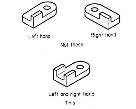
Avoid
designing mirror image (right or left hand) parts.1 When designing
paired parts, design with symmetry to save manufacturing time (since parts can
be stacked and machined in unison) and assembly time (because there’s no right
or left to track). If identical parts cannot
perform both functions, add features to both right and left hand parts to make
them the same. This tip also reduces
design time (half as many part models and drawings to create) and manufacturing
cost (making twice as many of the same part is always cheaper than making two
half-size batches of different parts).
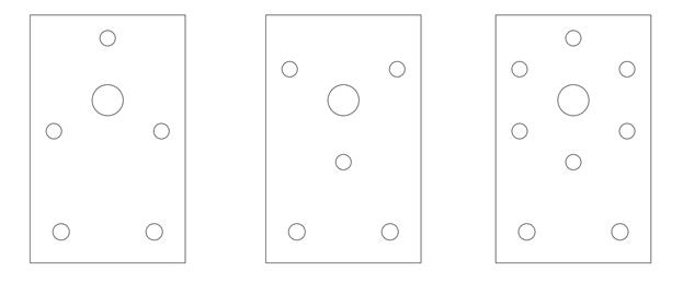
Figure 3:
Avoid mirror image parts
4.
Use larger
feature tolerances. ±
0.020″ is a lot easier to achieve than ± 0.005″, so use the loosest
tolerances possible and always investigate why they can’t be made larger.
Figure 4a: Tolerance
vs. production time
Figure 4b:
Improved design to reduce amount of grinding necessary
5.
Use fewer
and/or coarser surface finish specifications. Like finer tolerances, more stringent surface
finish requirements increase manufacturing time exponentially, so make sure you
can justify the magnitude of EVERY finished surface on a part or
instruct the manufacturer to leave it unfinished.
Figure 5:
Surface finish vs. production time
6.
Use fewer
dimension datums. Each
reference datum requires edge finding to locate a zero. Using fewer datums decreases setup time,
reduces error (tolerance) stack up and lowers the chances for mistakes.
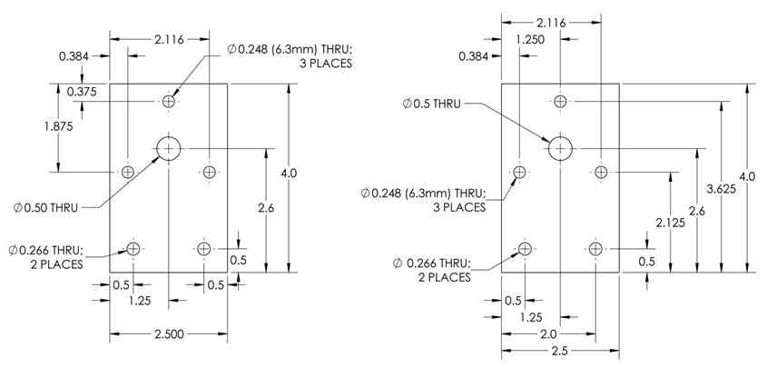
Figure 6:
Minimize dimension datums
7.
Use nominal
part dimensions. If
making the part manually, it’s much easier to read nominal dimensions off a
part drawing (i.e. 2.000 or 1.125 inches) than arbitrary dimension (i.e. 2.019
or 1.131 inches).
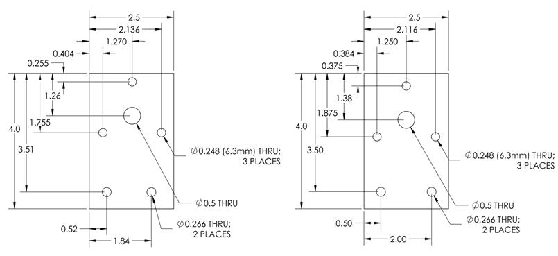
Figure 7: Use
nominal dimensions
8.
Use weaker
materials. Weaker materials
generally have higher machinability, so use them whenever possible. In addition, weaker materials typically have
a lower cost, which can be substantial.
Figure 8a:
Use weaker / cheaper materials
Figure 8b:
Use weaker / cheaper materials
9.
Use
thru-bolted holes.
Drilled clearance holes require less manufacturing time than threaded
holes, so use thru-bolted holes whenever possible to reduce part cost. On the flip side, when using thru-bolted
holes, you must be able to access the back of the part for assembly.
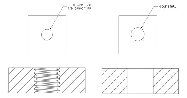
Figure 9: Use
thru-bolted holes
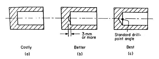
10.
Specify
cone-bottomed holes.
Cone-bottomed holes are produced by drills; flat bottom holes are
produced with end-mills. Drills are much
faster for producing holes and should be used exclusively unless you have a very
good reason to do otherwise.
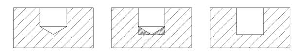
Figure 10a:
Use cone-bottomed holes, not flat-bottomed unless absolutely necessary
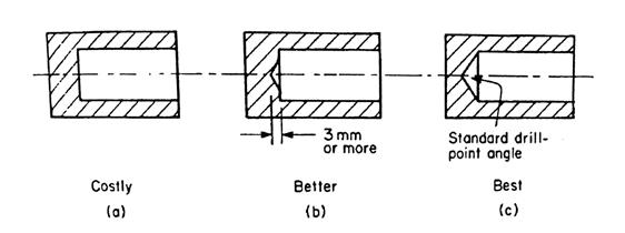
Figure 10b:
Cone-bottomed holes are the most economical; if flat bottom-bottoms are
required, some drill point depression in the center should be allowed if
possible
11. Make
the part smaller. If there’s no good justification otherwise,
make the part smaller; this reduces material cost, manufacturing cost and
leaves more space for other components in the assembly.
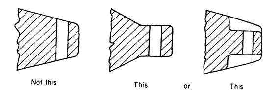
12.
Design for
minimum raw-stock removal. It
takes less time to remove less material.
Better designs start with material that is near net shape and minimize
the amount of machining operations. When
making a large number of parts from extruded raw stock, investigate having a
custom extrusion die made.
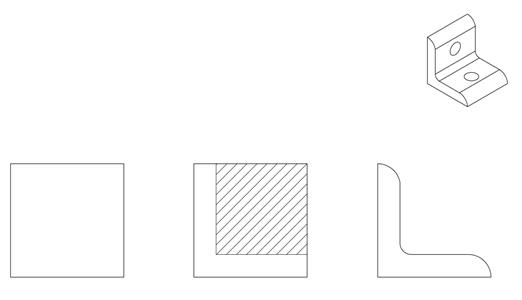
Figure 12a:
Design for minimum raw-stock removal

Figure 12b:
Commonly extruded profiles
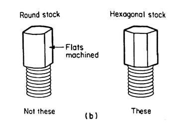
Figure 12c:
Use stock dimensions when possible to minimize the amount of machining (in this
case, hex. raw stock is used so flats don’t need to be milled into the part)
13.
Avoid small
cutting tools. Larger tools are
stronger and remove material faster without vibrating or breaking. Time is money when it comes to manufacturing,
so try to avoid designs requiring small tools.

Figure 13:
Smaller tools are always less productive
14.
Design for
favorable tool stiffness. Since
the strength and stiffness of cutting tools limit productivity, maximize
stiffness by minimizing each tool’s required length (L) relative to its
diameter (D). L:D
ratios should be under 3:1 for milling and 8:1 for drilling whenever possible;
smaller is always better.
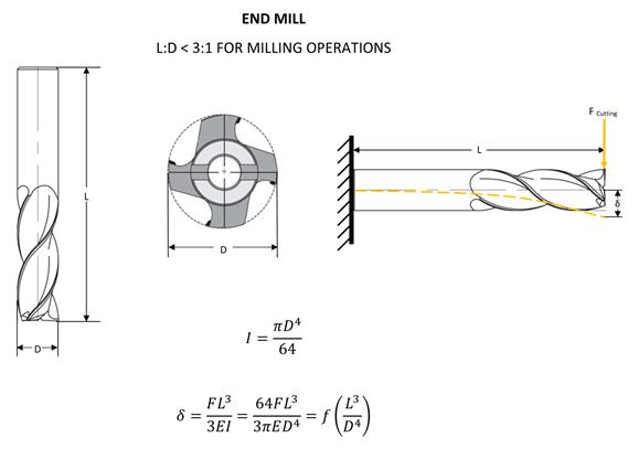
Figure 14a:
Select tools which minimize L:D ratios
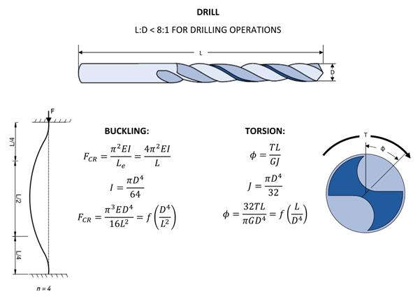
Figure 14b:
Select tools which minimize L:D ratios
15.
Design
around standardized cutter sizes.
If you can design features to use standardized cutter sizes, you can
often make parts on manual machines that otherwise would require CNCs. CNCs cost more per hour to operate, so for
prototyping, parts that can be produced on manual machines are typically
cheaper. In addition, custom cutters
normally cost 2 -5 times as much and can take weeks to receive.
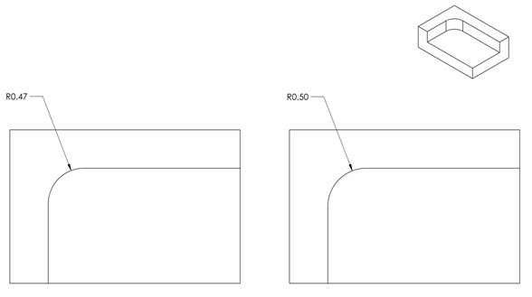
Figure 15:
Design around standard cutting tool sizes
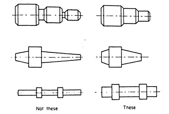
16.
Avoid
unnecessary fillets and contours.
Fillets look nice in a solid model but can add a LOT of expense in
secondary operations. Make sure fillets
are justified (i.e. in areas of high stress) because they can significantly
increase part cost and demonstrate ignorance or apathy if specified without
cause. Similar reasoning applies to
contours: simpler shapes require simpler processes and (manual) machines, so
whenever possible, try to avoid designing tapers, contours, and undercuts into
otherwise simple parts.
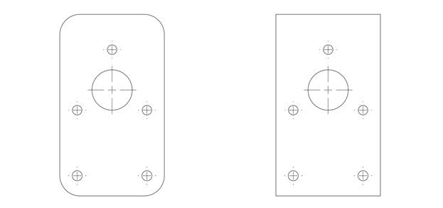
Figure 16:
Avoid frivolous fillets
17.
Show
Cartesian coordinates on detail drawings.
When dimensioning bolt circles (polar arrays), include Cartesian
coordinates so hole centers can be easily located when machining or programming
a CNC machine. If the manufacturer takes
time to calculate the coordinates, you pay for that time; so reduce part cost
by including coordinate dimensions on drawings as well as bolt circle
diameters.
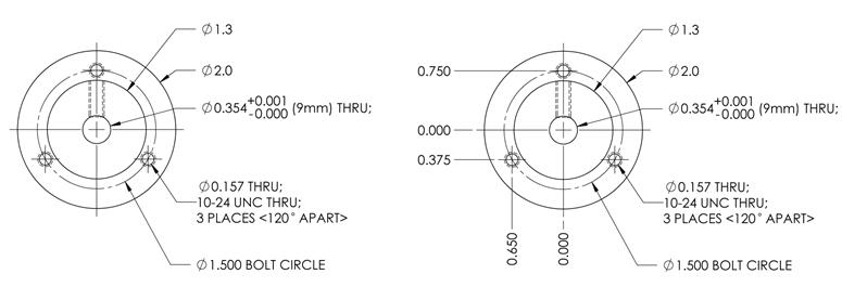
Figure 18a:
Always include Cartesian coordinates on detail drawings
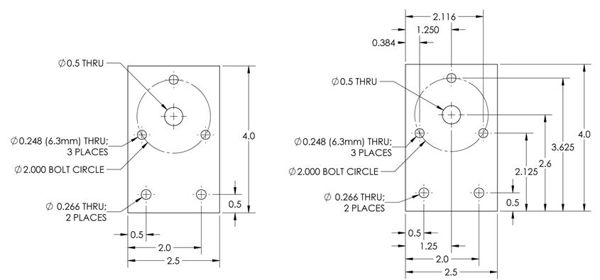
Figure 18b:
Again, always include Cartesian coordinates on detail drawings
18.
Design for
favorable part stiffness.2 The workpiece
must be rigid enough to withstand the forces of clamping and machining without
distortion, so try to avoid parts with thin walls or webs, or deep pockets, or
parts with unfavorable length to diameter ratios.
19.
Design the
part for convenient fixturing. Most machined parts are held in a vise or a
chuck, so try to design parts with compatible clamping surfaces to ensure rigid
and secure workholding.
20.
Avoid
undercuts and non-monotonic part features when possible3 , as these types of features require
additional machining operations which increase part cost
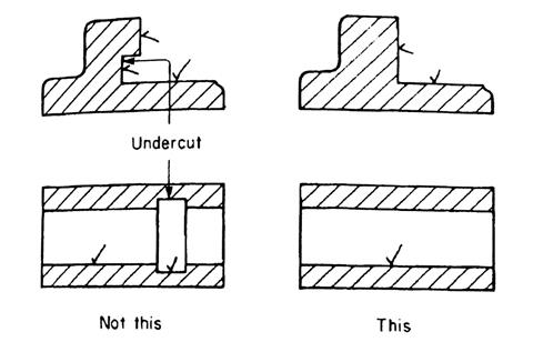
Figure 21a: Example of costly
challenging undercuts that should be avoided if possible
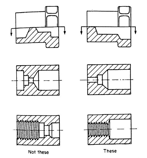
Figure 21b: Example of costly
non-monotonic part features that should be avoided if possible (i.e. all parts on
the left would need secondary chucking and machining, as opposed to being able
to be completed in one clamping operation
21.
Reduce the
total number of parts.3 The reduction
of the number of parts in a product is probably the best opportunity for
reducing manufacturing costs. Less parts implies less
purchases, inventory and handling. A
part that does not need to have relative motion with respect to other parts, does not have to be made of a different material, or
that would make the assembly or service of other parts extremely difficult or
impossible, is an excellent target for elimination. Some approaches to part-count reduction are
based on the use of one-piece structures and selection of manufacturing
processes such as injection molding, extrusion, casting, and powder metallurgy
(which are beyond the scope of this course).
22.
Consider
higher volume, lower cost-per-part processes. Machining is used widely for prototyping
parts, and where high precision is required in the final part. However, many mass produced parts can be
designed for higher volume manufacturing processes such as casting, forging,
stamping, forming, molding, and extruding.
Although these processes typically have higher initial setup costs, the
amortized cost-per-part is often much lower.
23.
Good designs
are elegant in their simplicity.
As stated eloquently by Dr.
Kevin Craig, create designs that are explicitly simple. Keep complexity intrinsic, buried, and
invisible. The less thought and less
knowledge a device requires for production, testing and use, the simpler it is.
24.
Treat each
drawing you create as a resume.
Good shops that manufacture parts for customers will always have enough work
to stay busy; in other words: they don’t need your business. Your drawings always compete against
others as job shops decide which to take on.
Many shops will refuse to quote parts that appear to be drawn by someone
who is inexperienced, ignorant or apathetic; OR they will add a nuisance cost
multiplier of 150% - 300% realizing you don’t know what you’re doing and you’re
going to require hand-holding to get the parts your project needs. So realize the impression drawings make on
others and invest time to present yourself as
intelligent, competent and organized.
Designing
for Assembly (DFA)
2 [return to top]
The following tips can help reduce the assembly
costs associated with a design. As with
most of the tips summarized in this document, every tip cannot apply to every
design. In addition, some tips may
result in higher manufacturing costs, so you must decide what is more important
or which gives the lowest overall final part cost.
The best design for assembly is usually the one that has the
fewest parts and the least costly type of fastening (consistent with the
functional requirements of the product).
1. Reduce / minimize the number of parts. Handling fewer parts typically results in
lower assembly times, and reduced supplier and inventory management. You’re almost an engineer, you can do it J!
Figure
1: Two designs for a fingernail clipper (example of simplifying)
2.
Make a major
product redesign. This
occurs when an assembly is redesigned so that the function supplied by one of
its components is achieved by another method.
One example would be the replacement of a threaded fluid system with a
system that uses quicker push-lock fittings.
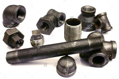
Figure 2a:
Fluid transfer system using threaded fittings (LEFT)
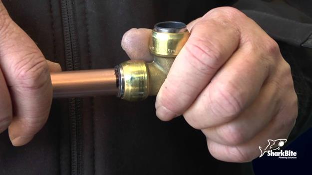
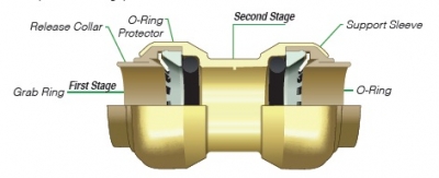
Figure 2b:
Fluid transfer system using push-to-connect (o-ring)
fittings
3.
Use a
different technology altogether.
Sometimes great benefits can be achieved when a drastic design change
enables a product function to be performed in a completely different
manner. This often occurs, for example,
when a mechanical device is replaced with electronics.
4.
Incorporate hinges. Hinges (or flexures) can be incorporated into
many plastic parts if the material is thin and flexible, thereby eliminating
the need for multi-part hinges, fasteners, and time required to
attach them to two other parts.
Many product storage containers are made with integral
/ living hinges.
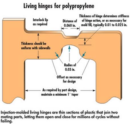
Figure 4:
Living / integral hinges
5. Incorporate integral springs. Springs can be incorporated into
a variety of parts, resulting in a simpler, faster assembly. Separate springs are often difficult to
handle and insert into the assembly.
Integral springs can therefore provide significant assembly advantages.
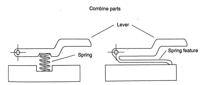
Figure
5: Integral springs
6. Incorporate
snap fits. Screw-type and other fasteners can often be
replaced with integral snap-fit elements, tabs, or catches using a variety of
materials, dramatically reducing assembly times.

Figure
6: Snap fits
7. Incorporate
guides, bearings, and covers. With some manufacturing processes, these
elements can be incorporated into the basic part with a tremendous reduction in
the number of components. Many plastic
materials have natural lubricity that make them suitable for applications
involving bearing surfaces, particularly if the velocity and pressure involved
are low. For more demanding
applications, porous metals like bronze or powder-metal parts can be used so
that lubricating oil is retained in the part itself.
8. Consolidate
electrical components. For example, one combination PCB is
preferable to multiple PCBs in separate locations; a light switch and fan
switch in the same mounting plate is preferable to locating them separately,
each with their own mounting hardware.
9.
Standardize
designs to use OTS fasteners and other parts. Use as few sizes and styles as possible and
reduce the total number.
10.
Use
subassemblies, particularly modular subassemblies, which can provide quality,
reliability, and serviceability advantages. Finally assembly is also simplified if it
involves only the placement and attachment of major modules. In addition, in many cases a particular
module can be applicable to a number of different assemblies, and thereby gain
the benefit of economies of scale of production.
11.
At the same
time, avoid too many levels of subassembly, since extra
subassemblies add overhead in the form of mfg. specs, floor space, and
inventory, and can actually increase mfg. throughput time.
12.
Design parts
so they cannot be inserted incorrectly.
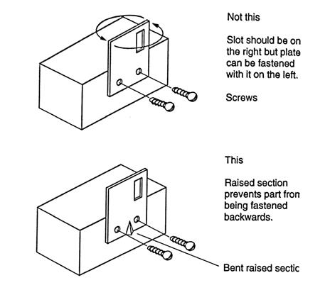
Figure
12: Design against improper assembly
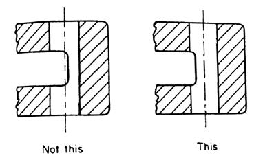
13.
Design parts
to be self-aligning / self-locating during assembly.
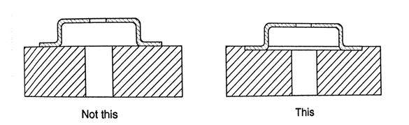
Figure 13a:
Use self-aligning / locating features
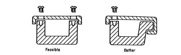
Figure 13b:
Minimize the number of fasteners by incorporating hooks or snaps into the basic
parts
14.
Eliminate
adjustments as much as possible during assembly.
15.
Use
funnel-shaped openings of holes and slots when possible to simplify mating part
insertion.
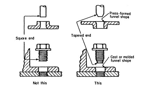
Figure
15: Use funnel-shaped openings and tapered ends to facilitate insertion of
parts
16.
When mating
parts have multiple through holes for fasteners, shafts, etc., use slots or
oversized clearance holes to allow for possible misalignment and quicker
assembly.
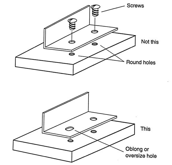
Figure 16:
Use slotted or oversized holes for quicker assembly
17.
Design parts
so they are easier to handle.
18.
As much as
possible, avoid designs that require parts to be manually held in place until
other parts are inserted.
19.
Use the
loosest fit possible between mating parts, consistent with product function, unless the
purpose of the tight fit is to hold the parts together.
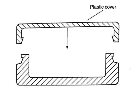
20.
Keep
internal mechanism accessible, or use a design that permits a housing cover to
be installed after all other assembly and adjustment operations are complete.
21.
Design small
parts so they can be inserted in as many ways as possible, from both
ends, if possible, with the least amount of angular orientation.
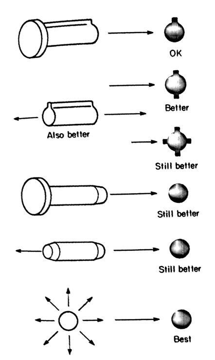
Figure 21:
Design parts so they can be inserted in as many ways as possible
22.
Avoid mirror
image (L & R) parts and subassemblies to speed assembly and reduce part
overhead.
Figure
22: Avoid mirror image parts
23.
Try to avoid
the use of components that can tangle when in mass prior to assembly (e.g. parts
with hook-like projections, and unnecessary holes and slots).
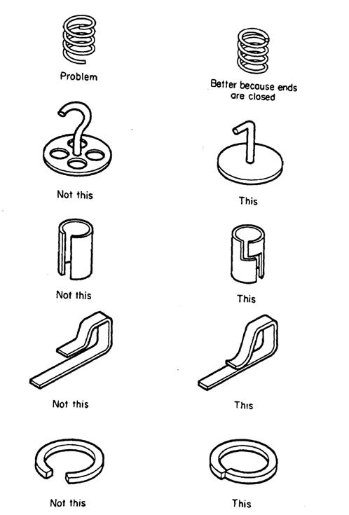
Figure 23:
Avoid parts that easily entangle
24.
Use snap
rings as an inexpensive way to fasten parts allowing freedom of movement, such as a
rotating shaft, as a separate retaining ring is often more economical than the
use of a headed pin due because of reduced machining cost.
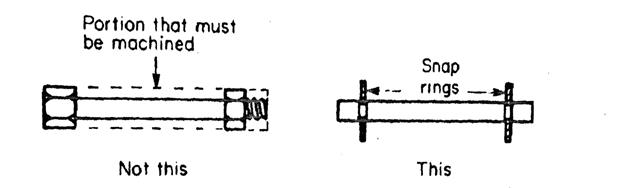
Figure 24a:
Using snap rings to avoid more costly machining
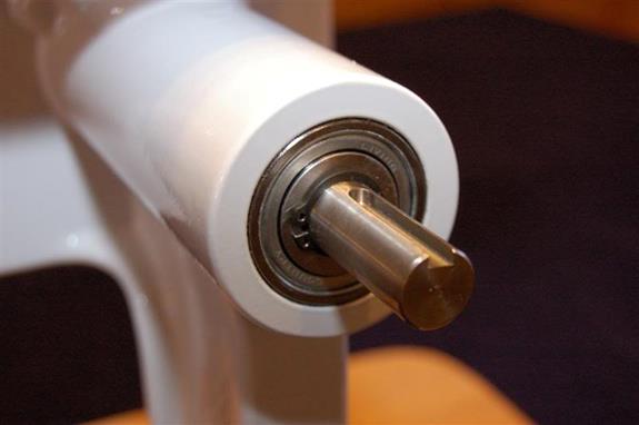
Figure 24b:
Using snap rings to secure bearings to a shaft without resorting to an
interference fit (which could damage a precision bearing)
25.
Occasionally
it pays to add parts to an assembly if doing so allows looser tolerances in the
component parts. An
example is a gear train with an idler gear whose position is adjustable, thus
obviating the need for extreme tolerances on the location of the gear-shaft
holes.
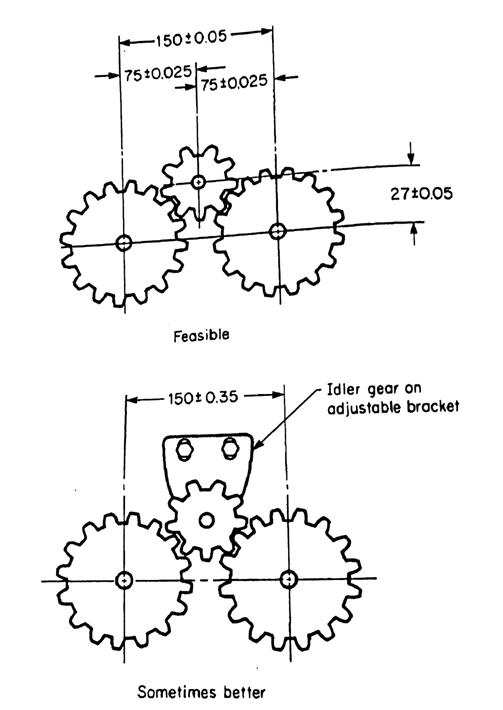
Figure 25:
Example of how adding a part can sometimes reduce complexity
26.
Use cast or
molded-in identification instead of attached labels because it
eliminates the costs involved in purchasing, stocking, and affixing separate
labels, and cannot fall off in use.
Designing for
Fastening (DFF) 2 [return to top]
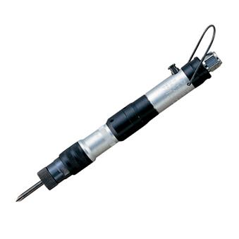
1.
Allow for
access to screw fasteners by efficient driving and tightening tools. Powered screwdrivers should have access
whenever possible. If not, the design should
permit the use of hand-powered socket wrenches.
Regular wrenches should only be used for holding a bolt head while the
nut is tightened.
2.
If hand
tools (i.e. wrenches or ratchets) must be used for tightening fasteners, permit
at least 60-deg of lever swing so sufficient tightening per stroke
can take place.
3.
When
possible, use fewer larger fasteners vs. more smaller
fasteners.
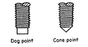
4.
If mating parts are subject to misalignment, use screws that provide a piloting
action and avoid cross threading, such as dog and cone points.
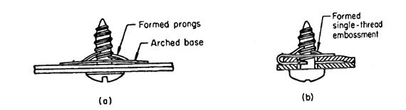
5.
Consider
self-tapping screws instead of nuts or threaded holes in mating parts. Threading is one of the most time consuming (i.e.
expensive) mfg. processes, so reduce or eliminate it for mass production.
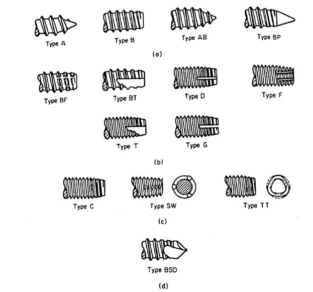
Figure 5: Self-tapping
screws: (a) thread-forming types, (b) thread-cutting types, (c) thread-forming types
for unified threads, (d) hole-drilling types
6.
Consider
rivets instead of screws for a lower-cost method of fastening parts together. Reference standardized design rules for rivets
(i.e. grip length, hole clearance, installation tool clearance, minimum edge
(tear-out) distance, backup washers, etc.), or you will look dumb.
Figure 6a: Recommended
minimum rivet-to-edge dimension
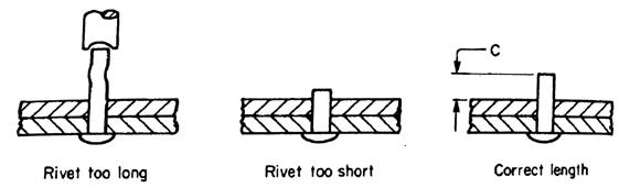
Figure
6b: Proper rivet length is critical and equal to the combined material
thickness plus the clinch allowance, c, which is approximately one half the
rivet body diameter
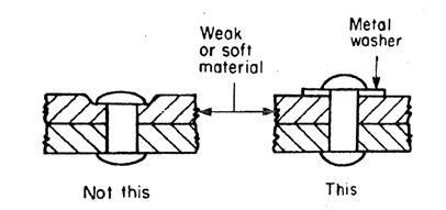
Figure 6c: Metal washers should be used to distribute the reactive force of
upsetting in weak, soft, or brittle materials (e.g. plastic, rubber, or
composites)
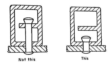
Figure
6d: The surface against which rivets are set must be well supported
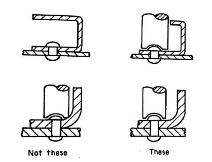
Figure
6e: Provide sufficient room in the assembly for rivet-clinching tools
7.
Consider drivescrews when strong holding forces aren’t required to
reduce hole-making and assembly costs.
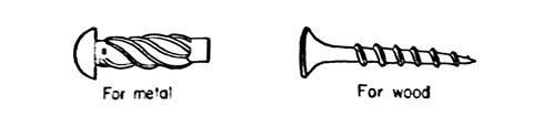
Figure 7: Drive
screws for metals and softer materials like wood
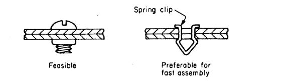
8.
Use push-on
fasteners instead of threaded fasteners if the axial loads are
low.
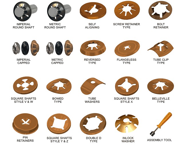
Figure 8:
Push on fasteners can be a good option when the shaft / pin needs to be held in
place, but not resist large axial loads
9.
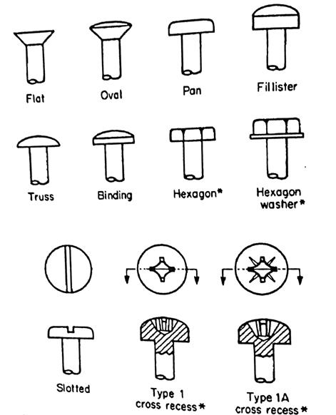
Select
fastener head types for ease of driving / torqueing). Hex, Phillips, and Torx
heads are the best. Socket (Allen) head
are higher in cost due to the required progressive heading die operation. Slotted head are the cheapest, but most
difficult to reliably drive, so avoid if trying to reduce assembly time.
10.
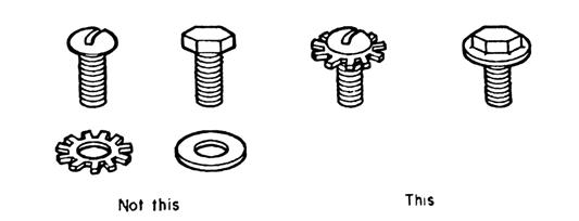
Use combined
fasteners (i.e. those with integral washers) to expedite assembly, procurement,
and stock handling.
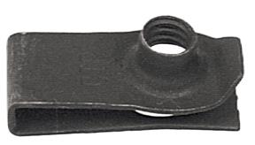
11.
Consider the
use of spring nuts when torque requirements are not high, because
this type of nut is inexpensive and easier to assemble.
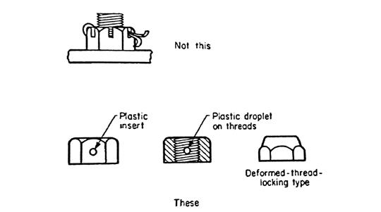
12.
If a locknut
must be used, avoid the use of slotted nuts and cotter pins, as these
are much more labor intensive than plastic or deformed-thread type locking
nuts.
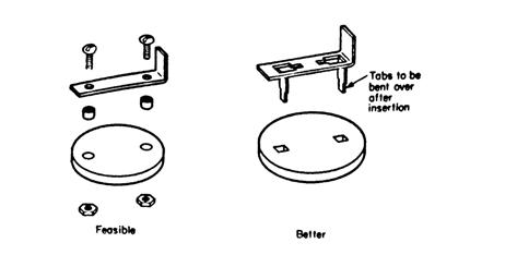
13.
Use bent
tabs or crimped sections instead of separate fasteners to hold several parts
together.
14.
Use integral
locators, hooks, or lips to replace some of the fasteners holding one part to
another.
15.
Press fits
or integral tabs can sometimes replace more complex fasteners. Press fits with flexible or grooved
components are normally less expensive and as effective as precision machined
parts.
16.
Consider
adhesives in lieu of fasteners.
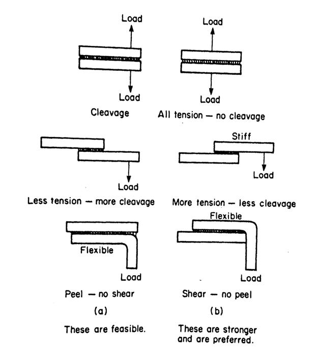
Figure 16a: Adhesives
favor shear, tensile, and compressive stresses as opposed to cleavage and peel
stresses
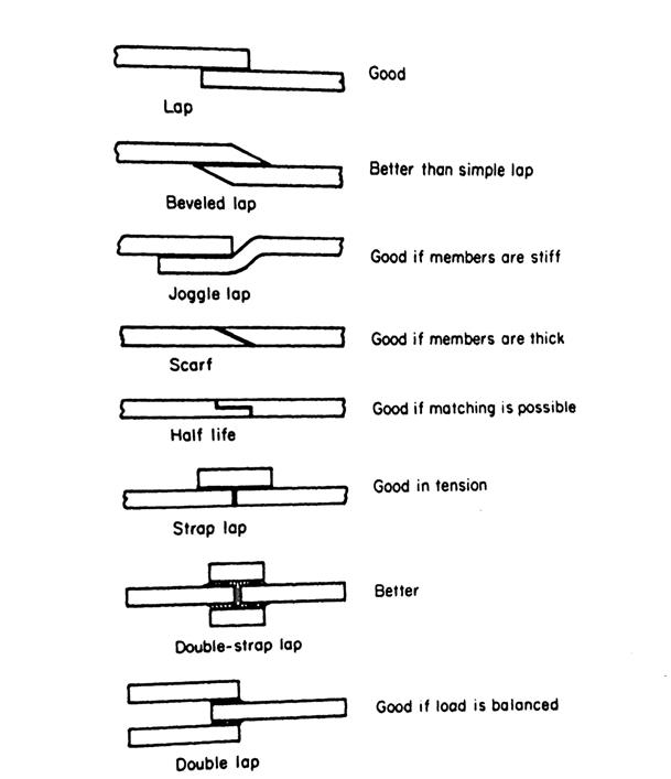
Figures
16b: Improved lab joints
Designing for Drilling2 [return
to top]
1.
Drill entry and exit surfaces should be
perpendicular to the drill bit to avoid starting and exiting problems, and help
ensure the hole is placed in the proper location.
2.
If holding straightness is important, avoid
interrupted cuts caused by intersecting holes unless a guide bushing can be
placed at each reentry surface.
3.
Use standardized drill sizes whenever
possible to avoid the cost of custom drills and drill grinding.
4.
Through holes are preferable to blind holes
because of improved chip evacuation.
5.
Avoid blind holes with flat bottoms.
6.
Avoid deep holes > 3xD because of
chip-clearance and hole straightness problems.
7.
Deep holes can be made using more expensive
processes like gun drilling and reaming.
8.
Avoid very small holes (< 1/8″)
whenever possible because small drills are quite fragile.
9.
If large finished holes are required, it is
desirable to place cored (cast-in) holes in the workpiece prior to the drilling
operation.
10.
If the part requires multiple holes, try to
dimension them from the same datum to simplify fixturing.
11.
Insofar as possible, design parts so all
holes can be drilled from one side of from the fewest number of sides to
simplify tooling and minimize handling time.
12.
Standardize the size of holes, fasteners, and
screw threads as much as possible so the number of drill changes can be
minimized.
13.
Use Cartesian or ordinate rather than angular
dimensions to layout holes because they are easier for the machinist to
interpret and less prone to error.
Recommended Tolerances
for Diameters of Drilled Holes
|
Hole
Diameter, in (mm) |
Recommended
Tolerance, in (mm) |
|
0 – 1/8 (0
– 3) |
+0.003 to
-0.001 (+0.08 to -0.025) |
|
1/8 – 1/4
(3 – 6) |
+0.004 to
-0.001 (+0.1 to -0.025) |
|
1/4 – 1/2
(6 – 13) |
+0.006 to
-0.001 (+0.15 to -0.025) |
|
1/2 – 1 (13
– 25) |
+0.008 to -0.002
(+0.2 to -0.05) |
|
1 – 2 (25 –
50) |
+0.010 to
-0.003 (+0.25 to -0.08) |
|
2 – 4 (50 –
100) |
+0.012 to
-0.004 (+0.3 to -0.1) |
Design for Reaming2 [return
to top]
1.
Never rely on reaming to correct position or
alignment discrepancies (use a boring bar or endmill instead).
2.
Avoid intersecting drilled and reamed holes
if possible to avoid tool breakage.
3.
If a blind hole required reaming, drill extra
depth to provide room for chips.
Recommended Tolerances
for Diameters of Reamed Holes
|
Hole
Diameter, in (mm) |
Recommended
Tolerance, in (mm) |
|
0 – 1/4 (0
– 6) |
±0.0005
(±0.013) |
|
1/4 – 1/2
(6 – 13) |
±0.001
(±0.025) |
|
1/2 – 1 (13
– 25) |
±0.001
(±0.025) |
|
1 – 2 (25 –
50) |
±0.002
(±0.05) |
|
2 – 4 (50 –
100) |
±0.003
(±0.08) |
Design
for Boring2 [return to top]
1.
Avoid designing holes with interrupted
surfaces, as interrupted cuts tend to throw holes out of round and cause
vibration and tool wear.
2.
Avoid designing holed with L:D ratios of over 5:1; otherwise, accuracy may be
compromised due to tool deflection. If
deep holes are unavoidable, consider the use of stepped diameters to limit the
depth of the bored surface.
3.
If a hole must be blind, allow the rough
drilled hole to be deeper than the bored portion by an amount equal to at least
one-fourth the hold diameter.
4.
Boring is more expensive than drilling or
reaming, so avoid it whenever possible.
5.
When boring as with other precision machine
operations, the part must be rigid so that deflection or vibration as a result
of the cutting forces is avoided. Care
must also be taken in the workpiece and fixture design to avoid deflection of
the part when it is clamped in the
fixture, for if this occurs, machined surfaces will be off location when the
part springs back from its clamped position.
Design for Welding2 [return to top]
1.
Welded
assemblies should be made up of as few parts as possible. Bending and forming operations are often less
costly than welding, so investigate (i.e. substitute or mix) accordingly.
2.
Weld
joints should be placed so there is room for easy access of the welding
gun/nozzle, especially when designing for GMAW, GTAW, or plasma cutting.
3.
The
design requiring the least weld metal and the least arc time is usually the
cheapest welded assembly.
4.
Whenever
possible, the assembly should be designed so the welded joint is horizontal,
with the electrode pointing downward during welding, as this is the most
productive and convenient position for all welding.
5.
Good
fit-up of parts at the weld joint is essential for welding speed and minimizing
joint distortion of the finished weldment.
The larger the gap filled with weld, the greater the possible weld
distortion. The extra operation to
provide a close fitting straight edge will typically be less costly than the
extra welding labor required when the fit is not correct.
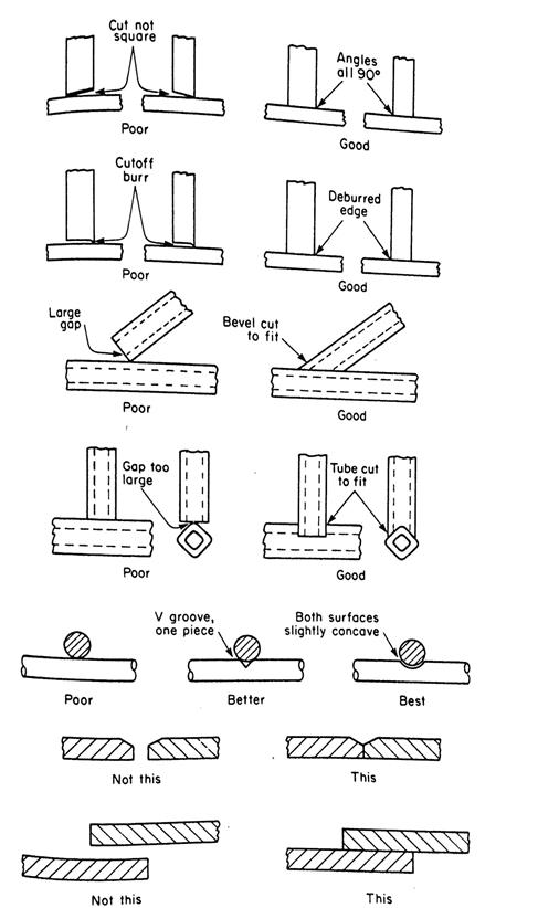
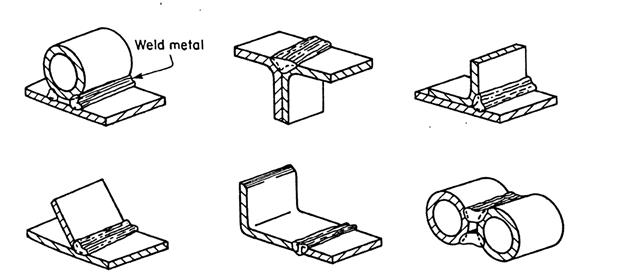
Figure 5:
Poor and good fit-up of weld joints
6.
Excessive
buildup of weld fillets should be kept to a minimum, as it does not add
significantly to the strength of the joint.
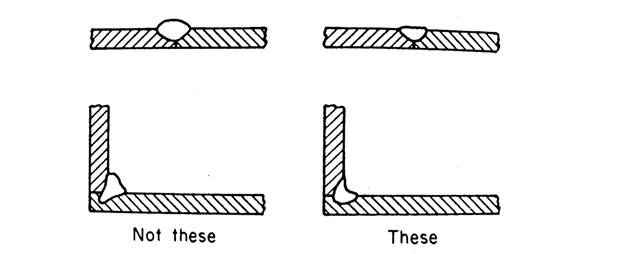
Figure 6:
Buildup of filler material does not add materially to joint strength
7.
It
is preferable to locate welds out of sight rather than in locations where
special finishing operations re required for the sake of appearance.
8.
The
joint should be designed so it requires minimal edge prep. It is often advisable to use slip or lap
joints in welding assemblies to avoid the cost of close edge prep and to
simplify fit-up problems.
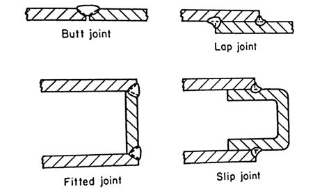
Figure 8: The joints on the right require less edge
preparation
9.
In
many cases, it is possible to use the curved edges or sides of parts comprising
the assembly to provide the equivalent of a grooved edge for the welded
joint. Since little,
or no edge prep is therefore needed, the total operation time is reduced.
Figure
9: Joints with natural grooves require little or no edge preparation
10. If post-weld machining is required,
welds should be placed away from the material to be machined.
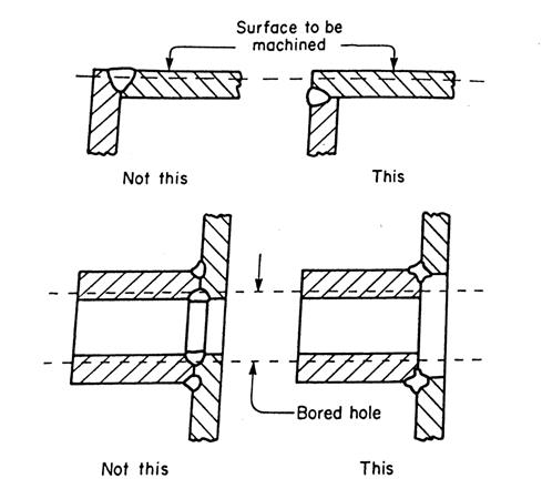
Figure 10: If
post-weld machining is required, keep the weld metal outside the portion of the
weldment which will be machined
11. It is often advisable to use a number
of welding subassemblies in the fabrication of a large, complex final assembly.
12. Heavier and stiffer sections are
generally less prone to distortion from welding, so designers should use their
mechanics of materials knowledge to help reduce post-weld distortion.
13. Long sections of thinner material
(e.g. sheetmetal), when welded together, are apt to distort and buckle unless
there is good rigid support for the joint.
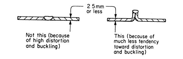
Figure 13: A
short-flanged butt joint is often preferable for joining thin material due to
reduced distortion
14. Whenever possible, place welds
opposite one another to reduce distortion by balancing shrinkage forces in the
weld fillets.
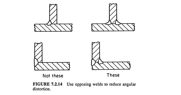
Figure 14:
Use opposing welds to reduce angular distortion
15. The butt joint is the most efficient
type of weld. If stock thickness is low,
or deep-penetration welding is used, the square-edge butt joint can be employed
and edge-prep time therefore saved. Thicker
stock or less penetrating methods may require grooved edges.
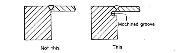 Figure 15a: Use machined groove to equalize
wall thickness to reduce distortion
Figure 15a: Use machined groove to equalize
wall thickness to reduce distortion
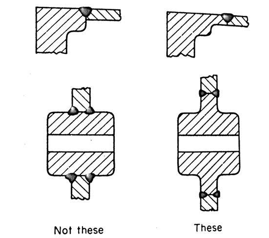
Figure 15b:
The wall thickness of parts to be joined should be equal at the weld joint
16. Always attempt to minimize the stress
the joint must carry. This can be
achieved by locating weld joints away from areas of stress or designing the
assembly so the parts themselves rather than the weld joints bear the load.
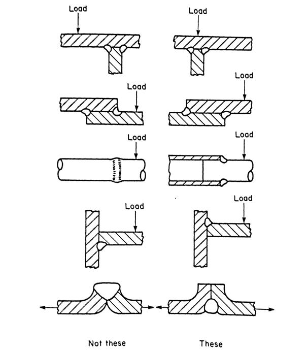
Figure 16:
Design weldments so welds are placed to minimize stress concentration in the
weld fillet
17. Fillet welds should be designed to be
in shear only; groove welds should be designed to be in either compression or
tension
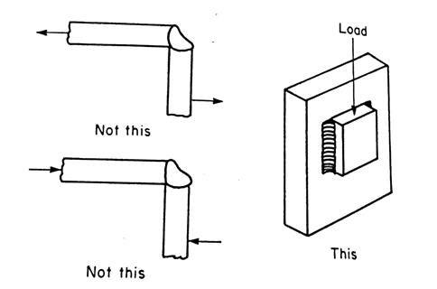
Figure 17a:
Fillet welds should be designed to be in shear only
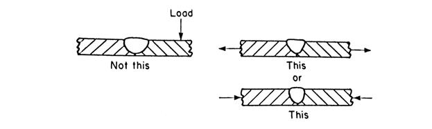
Figure 17b:
Groove welds should be designed to be in tension or compression only
18. When intermittent welds are used in
place of continuous welds for cost and distortion reduction, the length of each
fillet should be at least 4 times the fillet thickness and not less than 1-1/2″. If the joint is in compression, the spacing
of the welds should not exceed 16 times the thickness. If the joint is in tension, the spacing may
be as much as 32 times the thickness, but not over 12″.
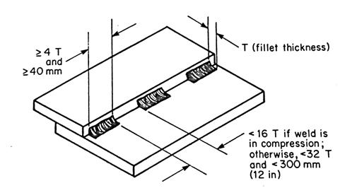
Figure 18:
Recommended length and spacing of intermittent welds
Design for Soldering & Brazing2
[return to top]
Soldering a and brazing are closely related processes in which metal
components are joined by means of a filler metal. The filler metal, which has a melting point
lower than that of the base metal(s), is introduced to the heated joint,
wherein it melts, wets the surfaces to be joined, and is distributed in the
joint by capillary action.
Soldered and
brazed assemblies represent configurations that are impractical or uneconomical
to make from a single piece. This may
occur when:
A.
Dissimilar
metals are involved, e.g. a carbide tool bit is brazed to a steel-alloy shank
for a cutting tool.
B.
Light
weight is important, but the shape is intricate, e.g. for an assembly of bent
tubing and fittings.
C.
The
part is too intricate to machine from one piece, especially because of thin
sections, and when high strength and accuracy are important.
D.
Hollow
shapes such as tanks, floats, or evaporators are involved. Leak-tight joints often dictate the use of
soldering or brazing.
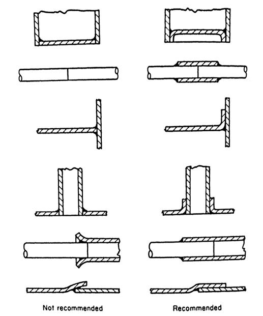
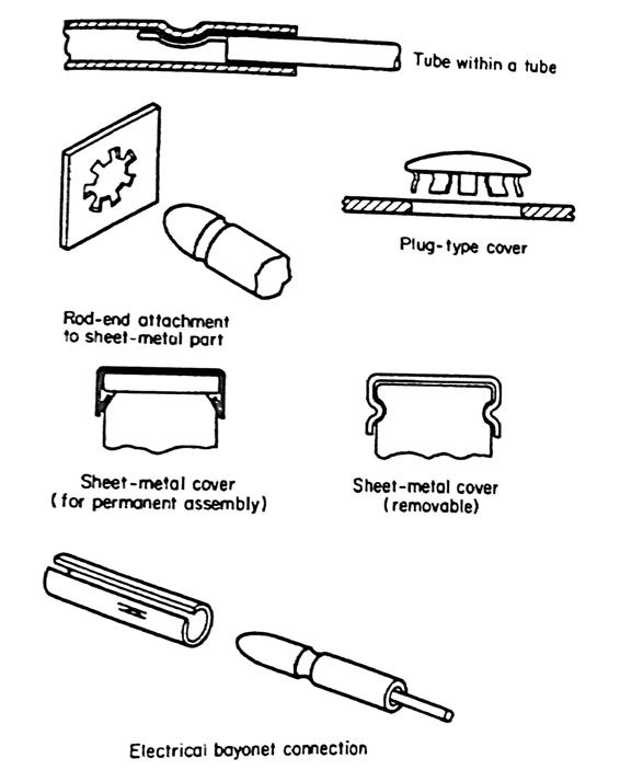
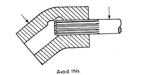
Figure 1: Joint configurations for soldering and brazing
Below
are a few design considerations and tips for soldering and brazing:
1.
Brazing and soldering are suitable for
a broad range of production quantities, ranging from one to tens of thousands.
2.
Brazing is applicable to a wide
variety of base metals—low
carbon steels, high carbon and alloy steels, stainless steels, copper, brass,
and nickel alloys.
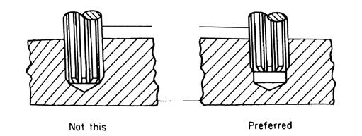
3.
Design joints which provide the
opportunity for filler metal to flow into the joint by capillary attraction,
which requires a close gap (0.003 - 0.008″) between surfaces of the
joint. In some instances, knurling permits
concentricity of the assembly to be maintained while still allowing room for
filler metal to flow by capillary action.
4.
Lap joints should be used whenever
possible because they provide an easy means for controlling the joint area and
gap, and usually do not present assembly or fixturing
problems. A rule of thumb for lap joints is to provide
an overlap of at least three times the thickness of the thinner member joined.
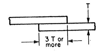
Figure 4:
Recommended lap joint dimensions
5.
Butt joints and scarf joints are not
recommended unless strength requirements are very low and there is no need for
a pressure seal at the joint.
Figures 5:
Lap, butt, and scarf joints
6.
The higher temperature of brazing can
cause distortion of the parts, so large, unsupported flat areas should be
replaced by curved or ribbed areas if possible, since the latter are more
self-supporting.
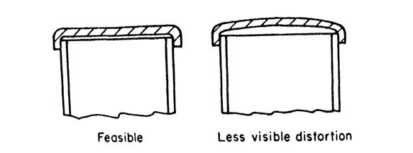
Figure 6: Use curved surfaces when possible to minimize
distortion
Works Cited
[return to top]
1. Anderson, David M. Design
for Manufacturability. n.d. webpage.
<http://www.design4manufacturability.com/DFM_article.htm>.
2. Bralla, James G. Design
for Manufacturability Handbook. McGraw-Hill Companies, Inc., 1999.
3. Greenlee, Bob. Design
for Manufacturing - Guidelines. n.d.
<http://www.unm.edu/~bgreen/ME101/dfm.pdf>.
Copyright notice: many of
the images and content on this page are taken from James Bralla’s
excellent Design
for Manufacturability Handbook, which does an excellent job organizing and
presenting it.