EML2322L TA INFORMATIONAL
ARCHIVE
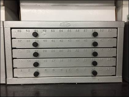
Quick Links (Table of Contents)
Project Motors &
Miscellaneous
Commonly
Manufactured Parts / Office Hours
Introduction / Purpose of Archive
[RETURN TO T.O.C.]
This
page should be thought of as the appendix to the TA notes and
training materials used in the course, in that it contains
supplementary information TAs should know, presented in a
graphical manner. As
you read these points, write down questions to ask during the
TA meetings / training sessions.
Items in black
are common knowledge TAs need to understand their first
semester working in DML. Items in red are less common, but
still important information TAs need to understand to
work effectively in the Senior Design Lab or Student
Shop.
Please submit ideas for
additional points here.
Design Guides
[RETURN TO T.O.C.]
1.
Power Transmission (Hub) Design Guide. Familiarize
yourself with the considerations for properly designing hubs
for use transmitting power.
2.
Motor Mount Design Guide. Familiarize yourself with
the considerations for properly designing brackets for
mounting motors and other components.
3.
Sheetmetal Design Guide. Familiarize yourself with
the considerations for properly designing sheetmetal parts.
4.
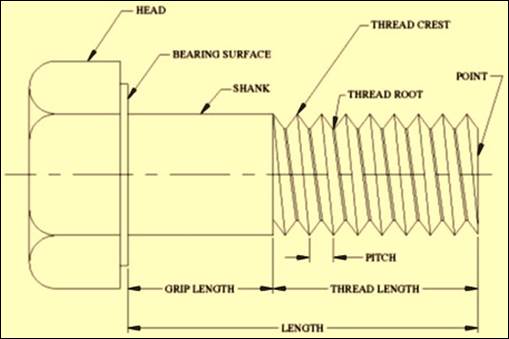
Fasteners Design Guide. Familiarize yourself with
the considerations for properly selecting and using fasteners.
5.
3D Printing Design Guide. Familiarize yourself
with the considerations and restrictions for 3D printed part
manufacturing in DML.
6.
AWJ Design Guide. Familiarize yourself
with the guidelines and design tips for AWJ manufacturing in
DML, as well as the requirements for submitted drawings.
7.
DFM Tips. Familiarize
yourself with the DFM principles introduced in DML.
8.
DFM Examples. Familiarize
yourself with examples of poorly and well
designed parts using the DFM principles introduced in
DML.
Milling Machines
[RETURN TO T.O.C.]
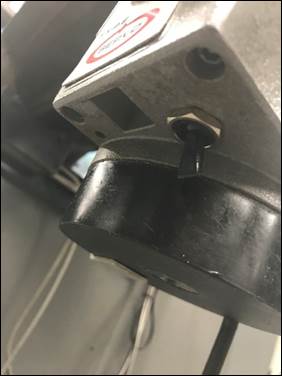
1.
Power
feed doesn’t function. Occasionally one of
the power feed units on the mills doesn’t function because
someone accidentally deactivated the power switch underneath
the unit.
2.
DRO
doesn’t update as table or saddle moves. The
occasional power surge will cause the DRO to freeze, and the
fix is to simply re-zero each axis.
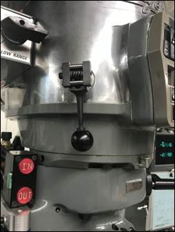
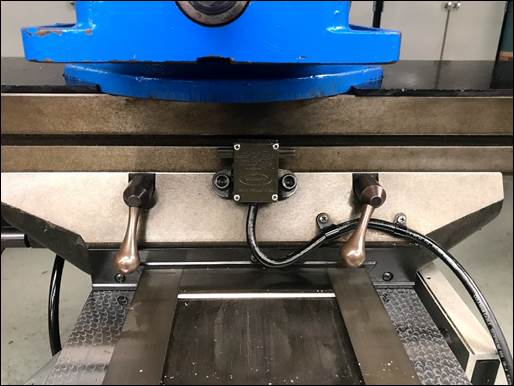
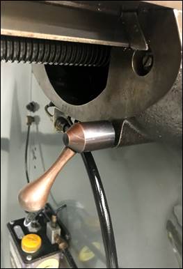
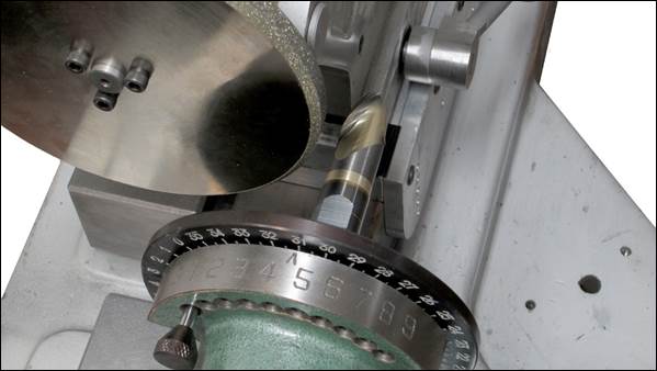
3.
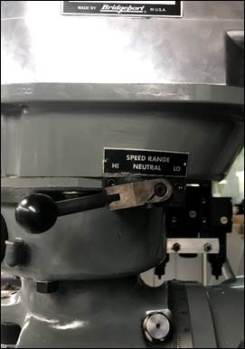
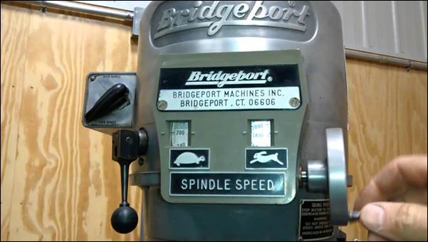
Switching
between HI and LO range. As a TA you will
need to be proficient switching the mills between HI and LO
range. This is not
trivial, so the first time you do it you MUST have Mike or a
TA present to ensure you do it properly. The following photos
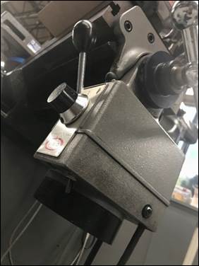
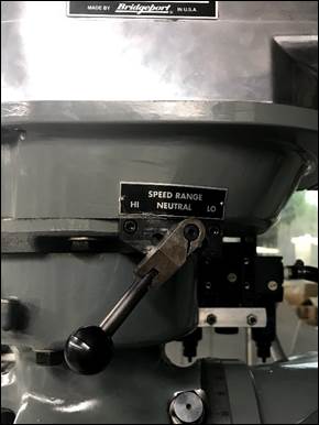
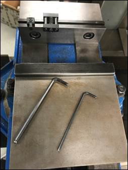
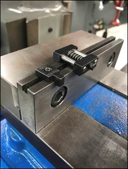
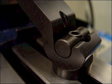
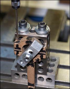
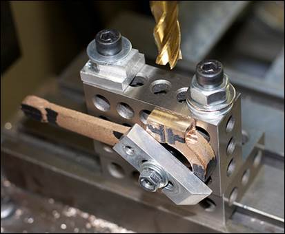
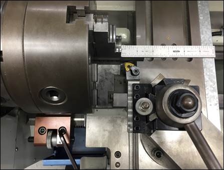
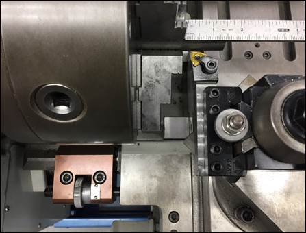
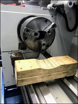
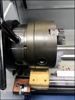
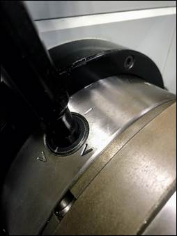
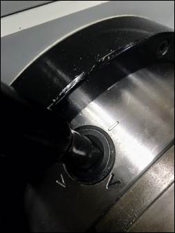
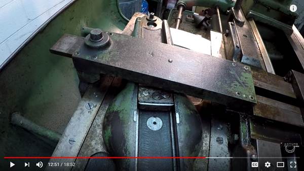
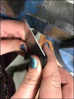
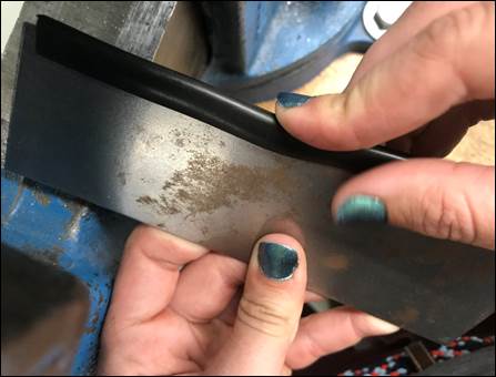
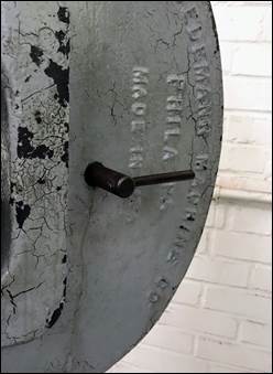
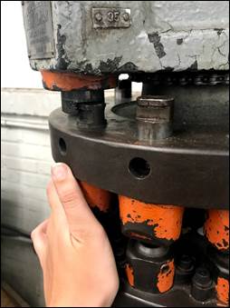
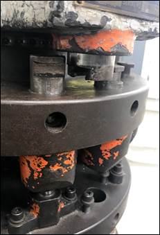
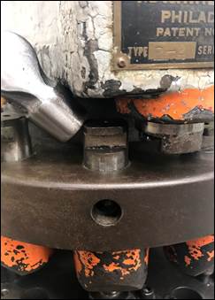
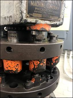
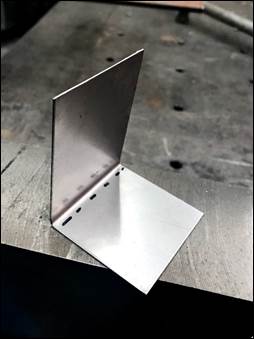
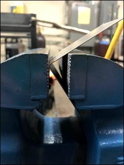
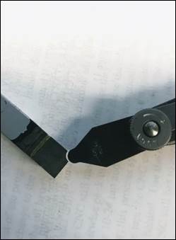
showing the right and wrong way of doing it should help. When switching speed
ranges it is always necessary to gently rock the spindle back
and forth to allow the teeth on the gears in the gearbox to
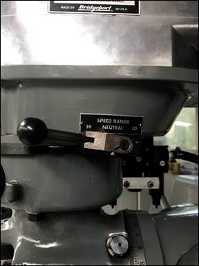
properly engage. The
first photo depicts the milling machine fully engaged in HI
range, the second photo shows the machine not fully engaged in
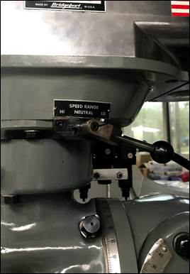
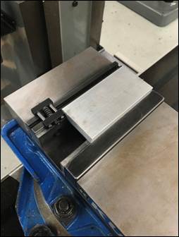
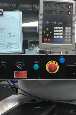
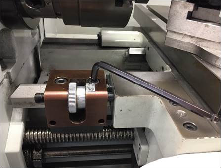
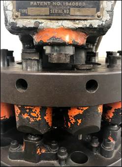
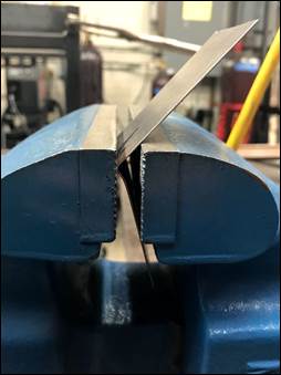
HI range. The
third photo shows the milling machine in neutral (this can be
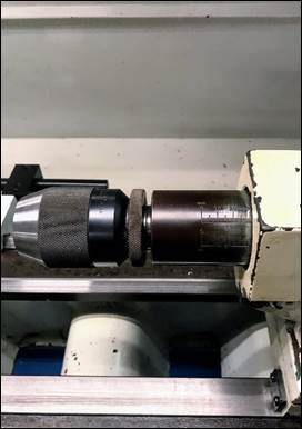
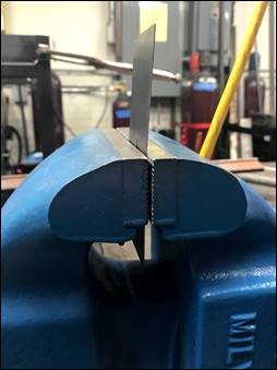
noted by the ability to freely rotate the spindle). The
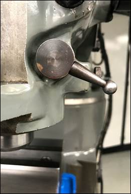
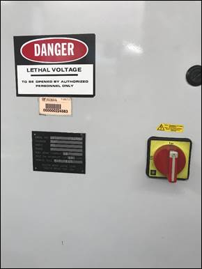
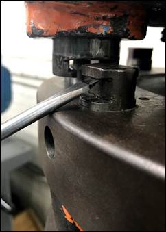
final photo shows the milling machine engaged in low range
(the spindle will be very difficult rotate by hand). Until
comfortable switching between ranges, always visually
compare the orientation of the range selector lever to
those on other machines before turning it on, to ensure
that it is fully engaged.
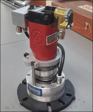
4.
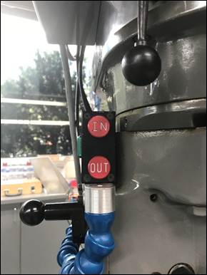
Power
drawbar doesn’t function or makes loud noise when retracting
spindle. Occasionally enough
moisture accumulates in the air lines supplying the milling
machines to prevent the pneumatic drawbar controls from
functioning. The
solution is to cycle the controls a few times (IN and then
OUT) until they begin working. Additionally, sometimes
the drawbar will make a loud rattling noise when the spindle
is raised to the uppermost position while running. This
noise is caused by a sticky pneumatic piston that engages the
drawbar during tool changes. The solution is to remove
the metallic black dust cover on the top of the unit and apply
some WD-40 lubricant to the outside of the piston so it once
again moves easily without sticking. When applying the
WD-40, cycle the piston manually by pressing it downward and
releasing several times.
5.
Fixing
power drawbar after a student fails to lock spindle before
installing/removing tool. When someone tries
to remove a tool without properly raising and locking the
quill/spindle, the drawbar jams and must be fixed. If this happens and
Mike is around, please ask him to fix it. Otherwise, the
technique is to raise the spindle as far as it will go (it
will likely not go all the way up, or it is not jammed), and
apply approximately 30 lb of upward force to the quill handle
while depressing the IN and safety buttons on the drawbar
controls in short 1-2 second bursts. With each burst the
quill should raise a little, until it is all the way to the
top of its travel and the quill/spindle lock can be properly
set.
6.
Fixing
speed control if student changes it while mill is OFF. When
someone tries to change the spindle speed when the milling
machine is not running, the adjustable width
pulleys
inside the gear head will pinch the drive belt, shortening its
life. The simple
solution is to try to return the speed adjustment dial to its
previous position without turning on
the machine. If you aren’t sure
of the speed at which it was formerly set, just adjust the
knob in the direction it easily moves until you feel increased
resistance to rotation. This
will be close to the position from which the student
mistakenly adjusted it with the machine turned OFF.
7.
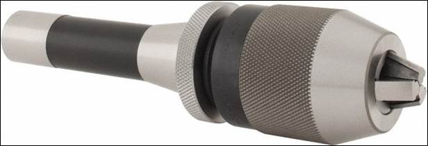
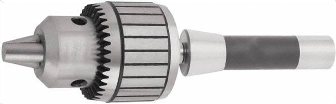
Keyed
vs. keyless chucks. We typically use
keyless chucks on our mills and lathes because most people
find them easier to use (in the past students pinched their
fingers in the chuck key gears when using keyed chucks). However, keyless
chucks are considerably more expensive and fragile than keyed
chucks, and should therefore only be used with drills up to ½”
in diameter. Above
this size, collets (which are always best) or keyed drill
chucks should be used. Keyed
drilled chucks should also be used for any tools requiring
additional cutting torque (such as hole saws) or any tools
requiring reversing of rotation direction (such as taps).
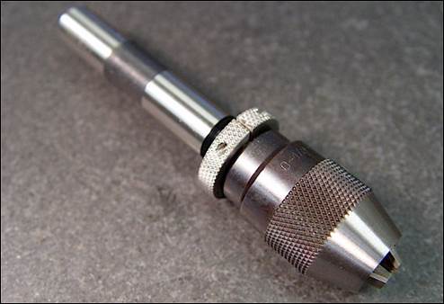
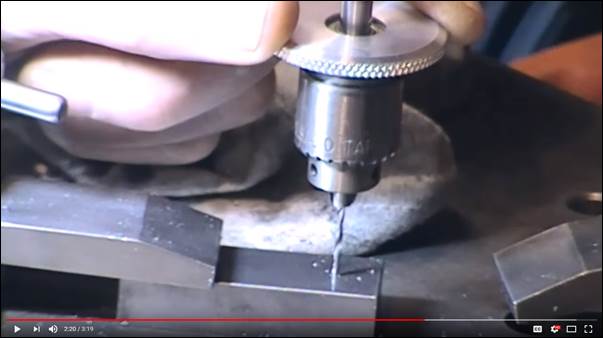
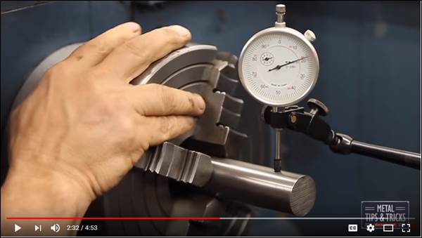
8.
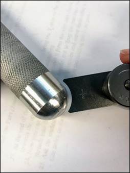
Micro drill chucks. These are useful
when drilling small holes (< Ø1/16”) where increased
sensitivity to axial thrust force is necessary to prevent
drill bit breakage. The
unique ball bearing design allows you to provide the drilling
force manually, as shown in the video below.
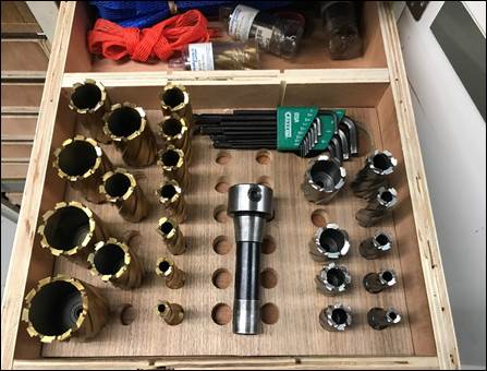
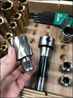
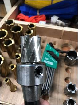
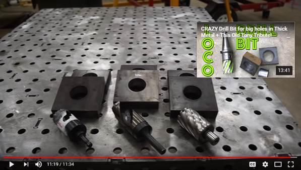
9.
Annular cutters. Annular
cutters
are located in the top drawer of the first lathe cabinet
(closest to the tall tooling cabinets behind the mills). The R8 mill arbors
are either located in the drawer or in the black plastic tool
caddy on the mill table.
Select the desired size cutter from the cabinet and
clamp on the Weldon (D-shaped) flat with the set screw in the
side of the arbor. Use
the 1/4″ Allen key to tighten the set screw on the flat on the
annular cutter (be careful, as if your hand slips, it can
collide with the cutter!).
The Speeds and
Feeds document
shows how to
calculate the cutting parameters for an annular cutter. Use copious amounts
of oil with annular cutters and do not feel them too
forcefully. Here is a video showing
their use.
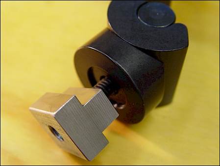
10. Workstops. Workstops
are used to preserve X-axis zeros for multiple parts or
operations (e.g. the Turner’s
Cube),
eliminating the need to re-zero each time an identical part is
reloaded. Workstops
are stored on each mill's spindle brake lever, on the front of
each mill vise, and in the mill accessories cabinet behind the
mills. The
procedure for use is to install a workstop on the fixed vise
jaw, set the initial zero on the part, machine the first part,
and when clamping the next part against the workstop, the same
X-zero is retained.
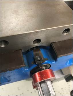
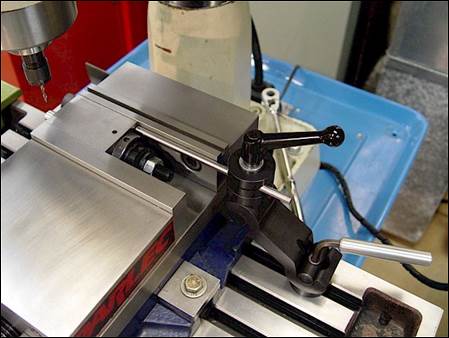
11. Spindle, saddle, and table friction locks. The mills have
friction locks for the spindles, saddles, and tables. The friction locks
keep the axes from moving under cutting forces. The spindle friction
lock (first photo) should always be used, unless you are
confident the threaded spindle lock is screwed up tightly
against the quill stop. The
table (second photo) and saddle (third photo)
friction locks should be used when performing drilling
or boring operations requiring high precision or producing
high cutting forces (e.g. when drilling holes large than ½”,
when using annular cutters, when using a boring head, etc.).
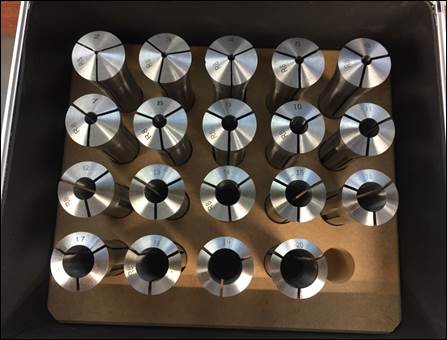
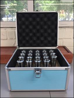
12. Metric collets. In
addition to the standard (imperial / inch) set of R8 collets
located on each mill there is a set of metric collets located
in the left grey metal cabinet. These are primarily used
for clamping endmills with metric sized shanks in the mills.
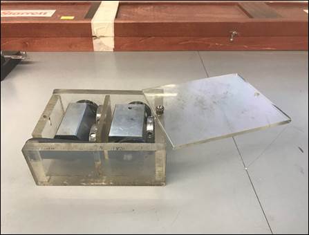
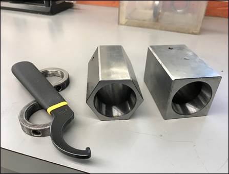
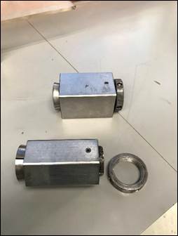
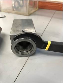
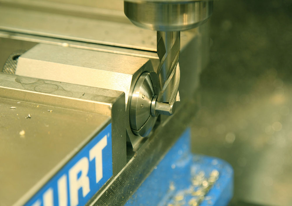
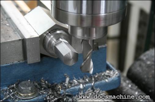
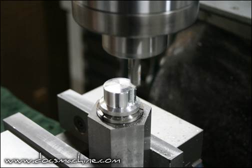
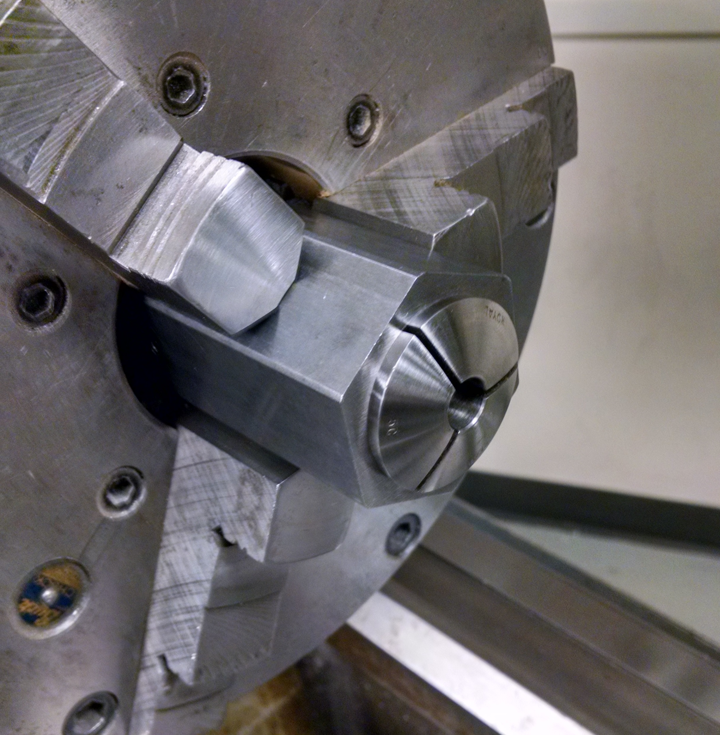
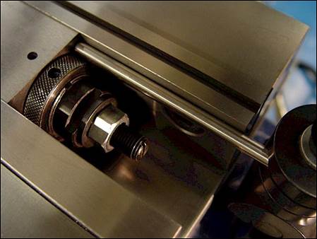
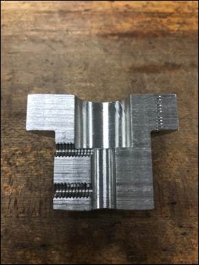
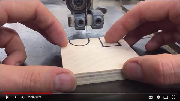
13. 5C collet blocks. The
5C collet blocks are located on the top shelf of the second
tall mill tooling cabinet (from the lab door) in an acrylic
box. The
available two holders are square and hexagonal in shape and
use 5C collets located in the gray cabinet in the NW corner of
the lab by the AC unit. These
collet blocks are used to cut opposing, square or hexagonal
features on round parts (e.g. a hex head on a fastener or
rod). Load the
appropriately sized 5C collet into the collet block, insert
the workpiece, and tighten the supplied collet nut using the
spanner wrench. NEVER
tighten down on an empty collet, as doing so will damage it. Here
is a video showing how to make a hex on a piece of round
stock using a 5C collet block.
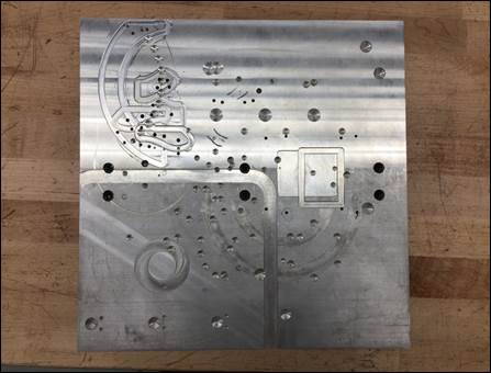
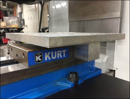
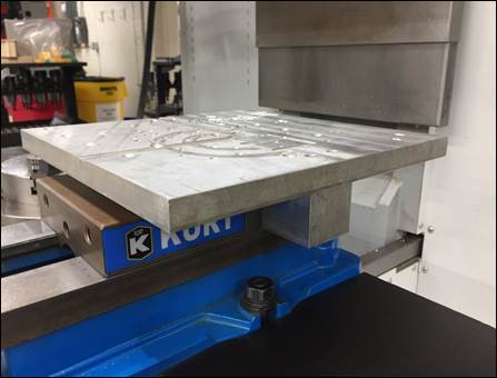
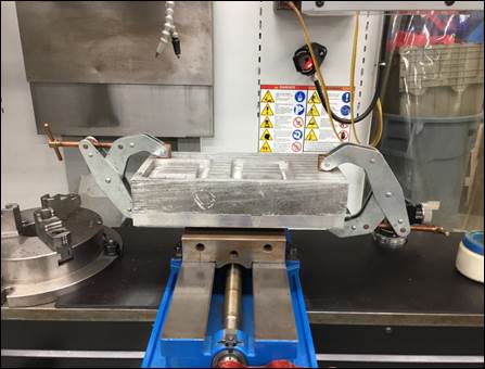
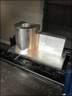
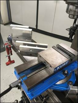
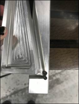
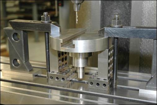
14. Jig plates. Jig
plates can be used when a workpiece is oversized for the table
mounted vises or when a workpiece is oddly shaped. Our jig plates are
located on the floor or shelf behind the TM-2 in the main lab
or in the bottom drawer of the tooling cabinet in the student
shop. To mount
the jig plate, clamp the lower portion of the T-shape into the
vise (2nd). To mount the workpiece to the jig plate
position the part as desired and use clamps (like the Kant
Twist in the 4th photo) to clamp the workpiece
securely to the jig plate (5th/6th).

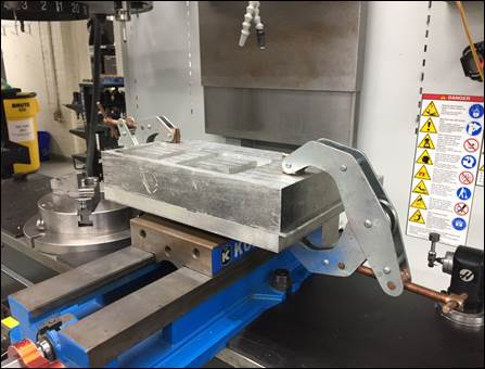
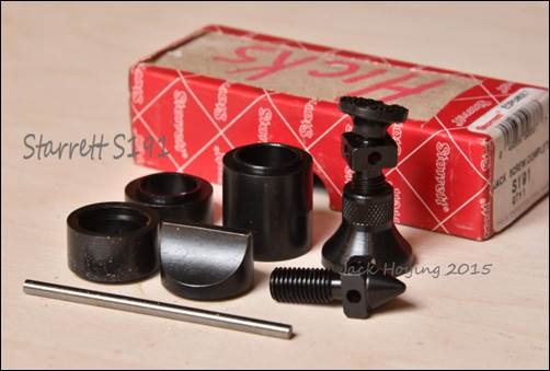
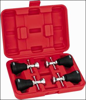
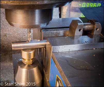
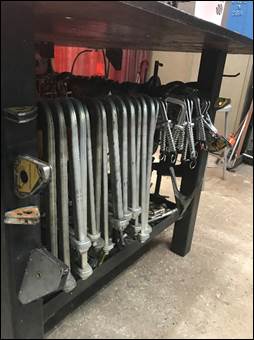
15. Machinist screw jacks. Sometimes
you
need to support the end of a flexible workpiece to resist the
cutting forces when machining.
Machinist jacks
are used for this purpose.
16. Heavy-duty workstop. In
situations
where the part or workholding prevents the use of the
previously discussed work stops, this type of workstop is
mounted to the back of the vise and is adjustable via split
shaft collars.

17. 5-axis workstop. This
is another type of versatile workstop which works well in a
variety of situations.
18. Alternative vise jaws. Depending
on the shape of the part and machining processes involved in
its creation, a variety of vise workholding jaws exist for
different applications. These
jaws can be found in the teal and beige cabinet located to the
left of Mike’s office door.
All jaws are installed using the same method of
removing the two bolts that attach them to the vise.
a.
Talon
jaws. When a part leaves only a very small amount of
material to clamp, the talons on these jaws will bite into
0.060” of the part with sharp knife-like edges. There are two
styles of Talon jaws: one set for cylindrical parts and one
set for rectangular parts; the orientation and distance
between the grippers can be adjusted by moving the talons
along the jaw. Here's a good video
showing their holding strength.
b.
Taller
& wider jaws. There are taller and wider jaws made of aluminum
and steel to clamp larger workpieces of various dimensions.
c.
Soft
jaws. For complex or difficult to hold parts the lab
stocks aluminum soft jaws, which are machined to match the
contour or geometry of the part(s) requiring machining.
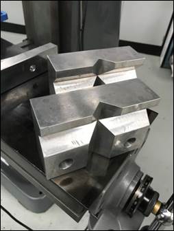
d.
Vee jaws.
Can
be used like the smaller v-blocks to secure cylindrical
workpieces in the milling machine in either the horizontal or
vertical direction.
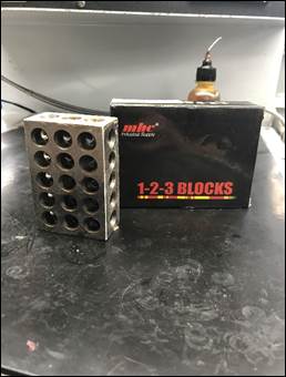
19. 1-2-3 blocks.
These are so named due
to their dimensions: 1”x2”x3”.
Like parallels, these blocks are precision instruments
and so can be used to ensure a part or tool set-up is parallel
to a particular surface datum allowing for quick fixture and
tooling set ups. These
blocks also have threaded and thru holes so that allow them to
be clamped to parts, fixtures, or machine tables.
Lathes
[RETURN TO T.O.C.]
1.
Southbend won’t turn on. Occasionally one of
the Southbend lathes won’t turn on because the student using
it previously activated the E-STOP button on the control panel
above the headstock or activated the foot brake, which in turn
activated the E-STOP circuit.
The former is corrected by simply resetting the E-STOP
button; the latter is corrected by lifting up on the foot
brake pedal so it is no longer activating the switch. Another reason the
Southbend may not turn on is because of the electrical service
disconnect switch located on the backside of the headstock is
turned off; rotate it to the “on” position to restore power to
machine. The
final reason the Southbend may not turn on is because of the
chuck guard interlock switch, which sometimes needs
adjustment.
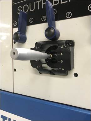
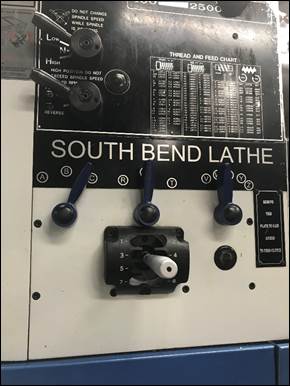
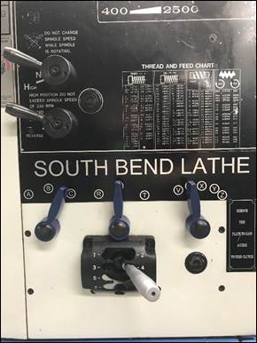
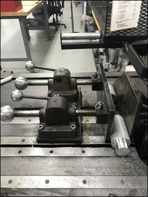
2.
Southbend power feed doesn’t function. Power feed rates on
the lathes are adjusted by changing the blue and silver levers
on the front of the headstock.
There is a thread and feed chart that shows what
combination of lever positions coincides with what feed rates. The feed rate levers
on the Southbends can be changed
while the machine is off or while it is running. Occasionally one of
the power feed units on the lathes doesn’t function because
the feedrate control levers on the front of the headstock are
not fully engaged. If
the silver handle isn’t fully engaged in one of the numbered
slots the power feed will not engage (compare the center photo
with the one on the right where the handle is engaged fully in
the slot). If the handle doesn’t want to fully seat in the
selected speed slot (typically LCS8W (0.007”/rev)) then rock
the chuck slightly until the handle fully seats itself (right
photo). The same
applies for the blue lettered levers; if the selection handle
is between two letters, the power feed will not function.
Here is a list of feedrates
that are appropriate for common materials when using the
lathes in our lab (assuming proper lubrication and part
stiffness):
|
Material |
Recommended
HSS Speed, V [surface ft/min] |
Recommended
Feed, f |
|
|
|
|
|
Acetal
(Delrin) |
250 |
0.010
and up |
|
Aluminum
and its alloys |
250 |
0.004
– 0.014 |
|
Brass
(360 free machining) |
200 |
0.004
– 0.014 |
|
Bronze
(high tensile) |
100 |
0.004
– 0.010 |
|
Stainless
steel (303 free machining) |
40 |
0.004
– 0.008 |
|
Stainless
steel (304 work hardening) |
20 |
0.004
– 0.008 |
|
Steel
(.2-.3 C) |
100 |
0.004
– 0.008 |
|
Steel
(.4-.5 C) |
60 |
0.004
– 0.008 |
|
Steel
alloys (300-400 Brinell) |
30 |
0.004
– 0.008 |
|
Titanium
alloys |
20 |
0.004
– 0.008 |
|
|
|
|
|
* multiply surface speeds in table by 2.5 for
carbide cutting tools * |
||
3.
Troubleshooting DRO errors. About once a year,
one of the Newall DRO
units
on the Southbend lathes will come out of calibration and the
X-axis motion displayed on the DRO will be incorrect. Here is a
brief document explaining how to reset the configuration to
the original settings.

4.
Radius vs. diameter. The Southbend lathe DROs are configured to
display part diameter, meaning if you zero the X-axis readout,
move the cross slide in 0.100” and make a cut, you will reduce
the part diameter by 0.100” (physically removing 0.050” off
the part radius). Most
lathes with DROs do this for convenience, so diameter
measurements can be directly compared to the DRO display (i.e.
if calipers show the part is 0.123” oversize, exactly that
amount needs to be removed according to the DRO display).
On the Ajax lathe
however, the cross slide vernier
dial references part radius, so if you move the cross slide in
0.100” and make a cut, you will reduce the part diameter by
0.200” (physically removing 0.100” off the part radius). This is an
important distinction to make when using (or instructing
other students on using) the Ajax lathe, or you will remove
twice as much material by accident!
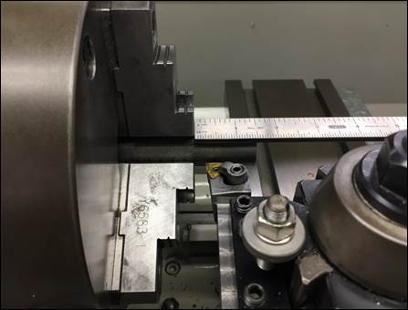
5.
Setting the carriage stop. An
important protocol to decrease the possibility of running a
tool into the chuck jaws is to ALWAYS set the carriage stop so
the cutting tool can't come any closer than a ¼” from the face
of the chuck jaws (1st). The carriage stop is
adjusted using an Allen wrench on the two fasteners located in
the top of the stop (2nd/4th). On the newer
Southbend lathe there is also a silver dial on the carriage
stop that allows fine adjustment. It’s important to
note the carriage stop will need to be adjusted to different
locations for different tools and should be adjusted
accordingly and never just relied upon. Always torque the
carriage stop screws as tightly as possible with the normal
Allen wrench.
6.
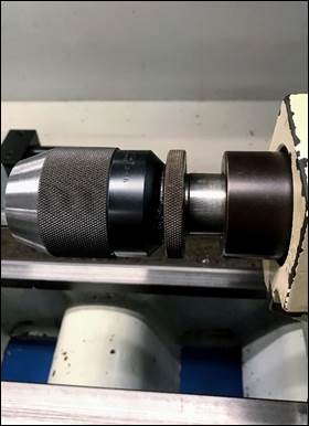
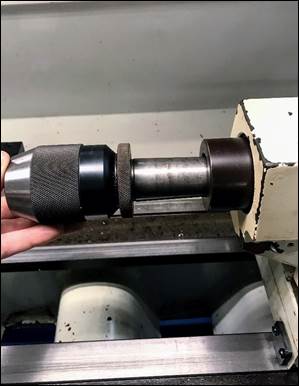
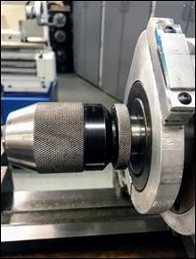
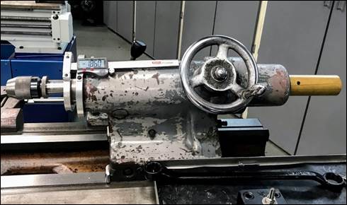
Loading and removing tailstock tools. It is frequently necessary
to change tailstock tools in the lathes. Common examples
include when using larger drills, when loading endmills to
produce counterbores, or when
installing keyed-style drilling chucks to hold taps for rigid tapping.
To remove a tailstock tool on the Southbend lathe,
securely hold the tool with your left hand (use a rag if it
contains a sharp tool, like an endmill), and retract the
tailstock quill until the tool is gently ejected. This
occurs where at the location where the quill color transitions
from shiny metal to darker oxidized metal. When
reinstalling tools in the Southbend, you must extend the quill
an additional ¼” beyond its extraction point, index the tang
on the backside of the toolholder to be loaded, and then
forcefully slide the toolholder into the tailstock quill.
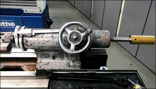
To remove a tailstock tool
on the Ajax lathe, engage the tailstock lock (so it doesn’t
slide along the ways), securely hold the tool with your left
hand (use a rag if it contains a sharp tool, like an endmill),
and bump the backside of the tool using the knockout rod until
the tool is forcefully ejected. The Ajax will accept a
tool in any orientation, so there is no need to phase tools
before installing. If
the toolholder you are installing contains a sharp tool, be
sure to use a rag to protect your hands.
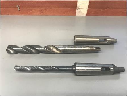
7.
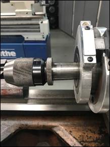
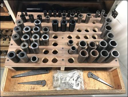
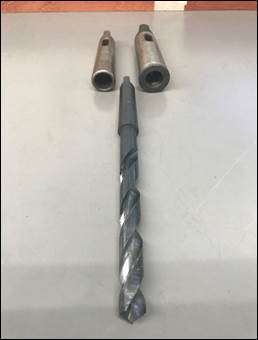
Taper shank drills. Large drills (> 0.5”) for
the lathes are located in the fourth lathe cabinet from Mike’s
door. These
drills have tapered shanks that transmit torque and allow for
quick installation. Depending
on their size, these drills are made with different size
tapers, which require adapters to fit a particular size
tailstock. Once
the appropriate adapter is selected, insert the drill into the
adapter, and install the drill with adapter into the lathe
tailstock in the same manner as the keyless chuck. After completing
your drilling operation, remove the drill from the taper
adapter with the wedge from the same drawer as the adapter (1st)
by inserting the wedge into the slot at the back of the taper
adapter and apply upward force on the wedge until the drill is
released from the adapter sleeve. Tap the wedge on a
piece of scrap wood, never on top of the gray laminate
tabletops.
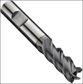
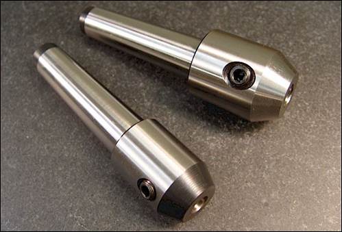
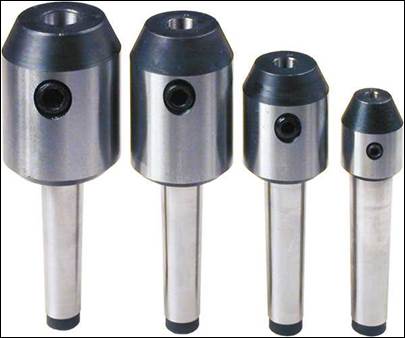
8.
Endmill holders.
The
general term endmill
holder refers to a toolholder that allows an endmill to
be clamped using a set screw against the provided Weldon flat
on its shank (providing positive mechanical engagement). When used in lathes,
these holders have a morse taper geometry that is compatible with all lathe tailstocks. When
loading/unloading an endmill holder containing an endmill,
always use a rag to protect your hand from serious injury and
do not touch the precision tapered portion of the toolholder
because the moisture on your hands will cause it to rust.
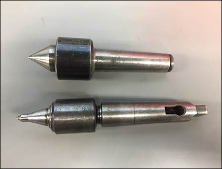
9.
Live and dead centers. Typically
found
on top of the lathe cabinet, live or dead centers are used to
provide support to longer workpieces where deflection will
cause poor dimensional accuracy and surface finish. A center is mounted
in the tailstock (sometimes a center can be mounted in the
headstock this technique is called “turning between centers”)
and mates with a matching hole drilled by the appropriate
sized center drill. A dead center (2nd) is a center
that does not freely rotate; when a dead center is engaged it
produces friction between the center and the workpiece; to
prevent friction welding a lubricant is placed on the end of
the dead center. A live center (1st) rotates
with the workpiece due to the inclusion of internal bearings
to allow the end to rotate.
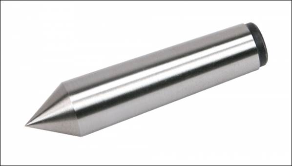
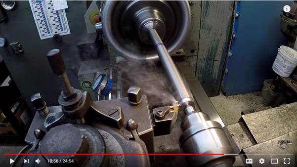
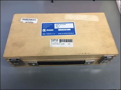
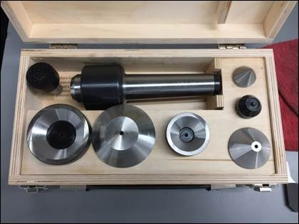
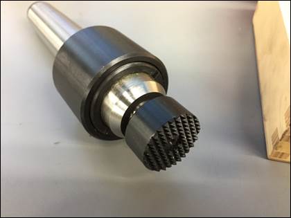
10. Skoda live center. This
live center differs from the previously discussed centers due
to the end being interchangeable between a variety of end
styles and shapes (conical, inverted cone, and flat serrated).
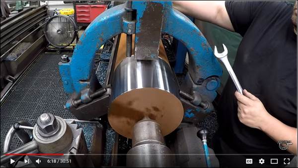
11. Steady rests. Steady
rests are used when cutting shafts with long
length-to-diameter ratios.
As seen in the following videos, they are used in
conjunction with tailstock centers.
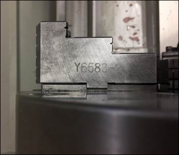
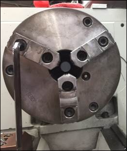
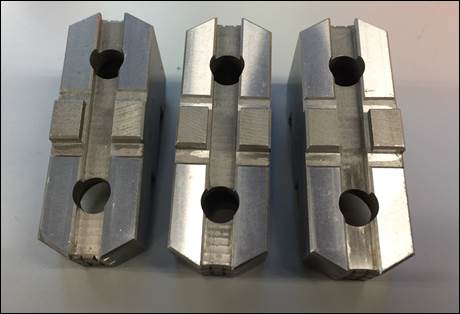
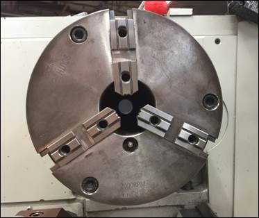
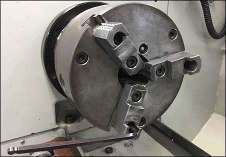
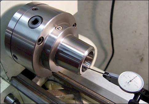
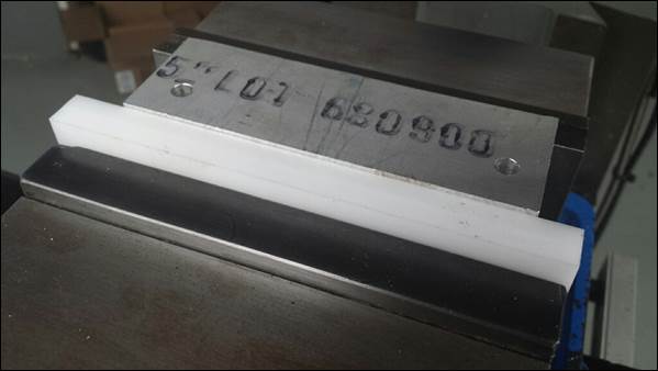
12. Reversible chuck jaws. To
accommodate
larger diameter workpieces, many lathe chuck jaws can be
reversed to increase the allowable clamping diameter. Good chuck jaws have
two halves: a master jaw that engages the scroll inside the
chuck body (allowing the three jaws to open and close
synchronously when adjusted with the chuck key) and a top jaw
that bolts to the top of the master jaw and clamps against the
workpiece (1st).
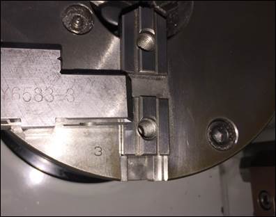
Most top jaws can be removed and rotated 180 degrees to
clamp larger work. However,
the factory hardened top jaws correspond with a particular
master jaw, so be sure to match the number stamped on the jaw
with number stamped on the chuck body (5th).
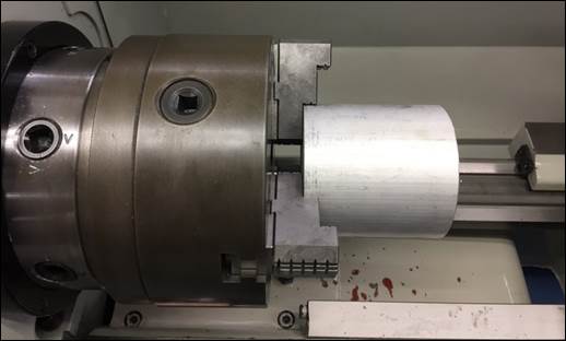
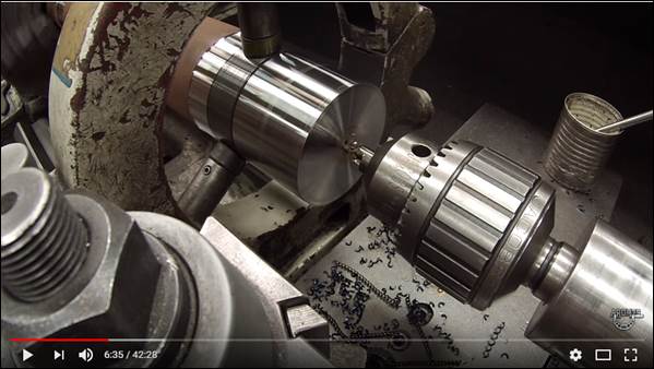
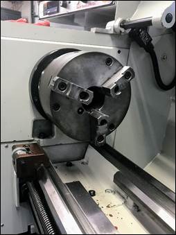
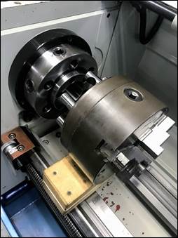
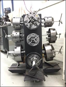
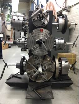
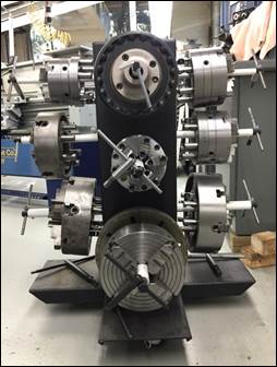
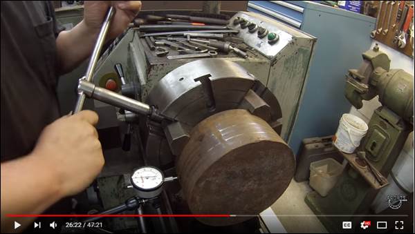
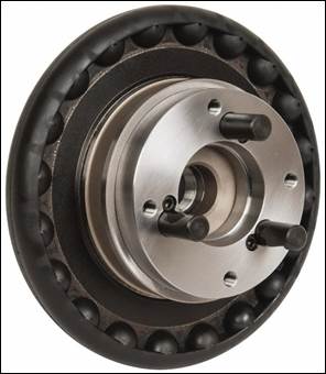
13. Changing chucks. As
explained in the next point below, there are a variety of
chucks which can be mounted to the engine lathe spindles for
use cutting different shape workpieces. Consequently, it’s
necessary to know how to change chucks without damaging the
irreplaceable precision ground spindles. As seen in this
instructional video, the process requires good
upper body strength and close attention to detail.
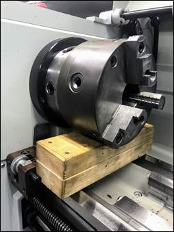
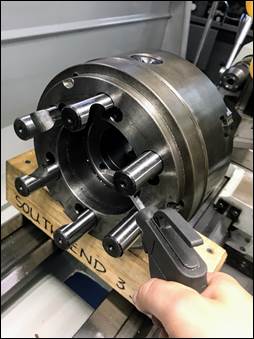
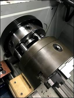
When
removing the existing chuck mounted to the spindle, place a
piece of wood on top of the ways to prevent damage if the
chuck accidentally drops.
Pieces of wood have been contoured to match the
commonly mounted 8” chucks and can typically be found on top
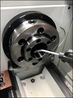
of the chuck cart. To
separate an existing chuck from the spindle, take the smaller
chuck key handle which fits the first ring on the spindle and
turn the square pins from their initial position between the
two “v”-notches to the notch at the 12-o’clock position
releasing the locked pins.
After all the pins are released the chuck will be able
to slide from the mounting plate. Sometimes the chuck
will need to be tapped with a plastic mallet to release it
from the spindle taper.
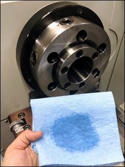
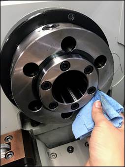
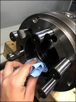
When installing a chuck, cleanliness is critical. Use the air to
blow off the spindle nose, and blow out of the mounting
end of the chuck to be installed. Then use a new
blue paper towel with a little oil on it to wipe off any
remaining chips or debris from the mounting surfaces. Finally, when
installing the chuck, be sure to not bump the precision
ground surface on the face of the spindle nose. Remount the new
chuck following the same procedure used for removal, being
careful to lightly tighten the cam locks evenly to allow
the chuck to sit flush with the end of the precision
ground spindle.
Please do not change chucks
without first obtaining permission from Mike.
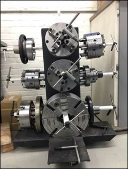
14. Alternative lathe chucks. Located between the Hardinge
lathe and the lathe cabinets is a large storage cart for the
chucks available in lab.
Included on this cart are three jaw, four jaw, six jaw,
and collet chucks. Four
jaw chucks allow clamping of non-cylindrical workpieces and
are available in two types: scroll (all jaws move at the same
time) or independent (each jaw moves independently of the
others and has to be indicated for proper alignment). Six jaw chucks are
ideal for clamping thin-walled materials like tubing due to
the clamping force being distributed over six jaws, and
prevent the material from being crushed when used correctly. Collet chucks are
beneficial due to their safer design (no protruding jaws and
can operate at higher speeds) and the fact that they don’t mar
the workpiece surface like normal chuck jaws; however, collet
chucks are limited in collet size (1-3/4” diameter) and only
nominal size workpieces can be clamped (the stock can only
deviate ±0.002” from the specified collet size).
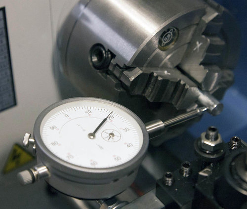
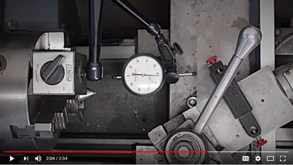
15. 4-jaw chucks. 4-jaw
chucks are useful on lathes because they can be adjusted for
better accuracy than any auto-centering (scroll) chuck, they
provide more robust workpiece clamping when roughing, and they
allow oddly shaped parts to be securely clamped. The downside to
4-jaw chucks is they take longer to use because parts must be
indicated to run true (“on center”), however, with a little
practice the procedure is quite easy and even quite enjoyable. The first photo
below links to a step-by-step procedure for indicating a part
in a 4-jaw chuck and the second two thumbnails link to good
videos showing the procedure.
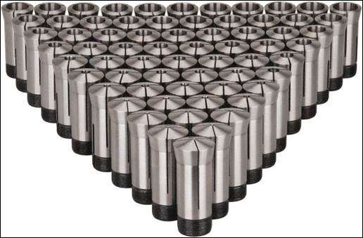
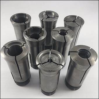
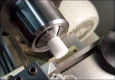
16. Collet chucks. Collet
chucks use collets similar to those that hold tools inside the
manual milling machine spindle, but in this case they are used
to hold precise workpieces in the lathe while very evenly
distributing the clamping force around the entire perimeter of
the workpiece. The
most common collet sizes for manual machines are 5C and 3J. 5C collets are
limited to Ø1-1/8” material and 3J collets are limited to
Ø1-3/4” material; they are
available for holding English and metric size workpieces; and
blank “emergency” collets are available which can be machined
to any desired size / profile.
The workpieces used in collets must be within +/-0.002”
of the nominal collet size or the collet can be damaged and
the work will not be clamped properly. Collets are
available in round, square, and hexagonal shapes.

17. Cutting tapers using the compound
slide. Each of the engine lathes in
our lab have an adjustable axis on top of the cross slide that
is used to cut compound angles.
Below are a few videos showing how to adjust the
compound slide to cut a short taper into a workpiece.

18. Cutting tapers using the taper
attachment. Longer tapers may be cut
using the taper attachment found on the Ajax or one of the
Southbend lathes. Below are a few videos showing the
process.

Commonly Manufactured Parts /
Office Hours
[RETURN
TO T.O.C.]
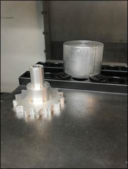
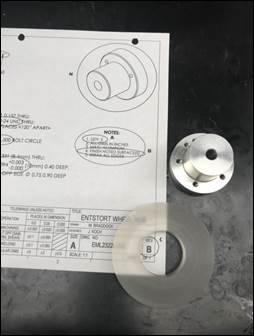
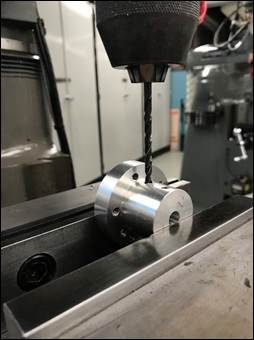
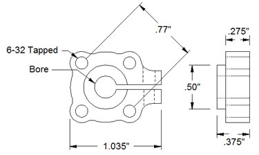
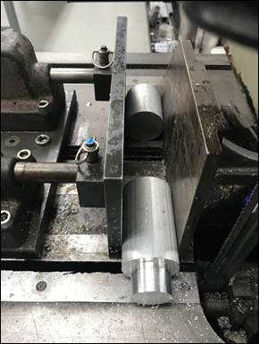
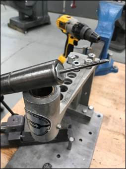
1.
Entstort
Counterbore. When producing the
0.75″ counterbore for the Entstort wheel hub, DO NOT rotate
the spindle slower than 250 RPM, as doing so when modifying a
part that contains cross-drilled holes (e.g. the assigned
wheel hub) can cause the chipload
(and therefore the torque) on the endmill to suddenly spike
and shatter the cutting tool.
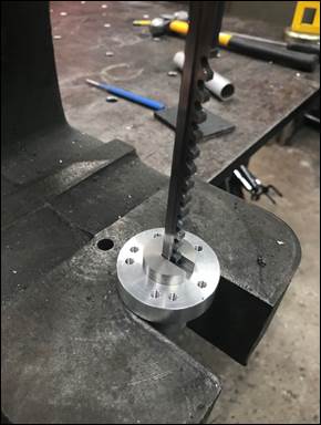
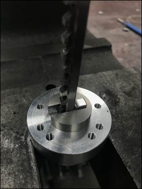
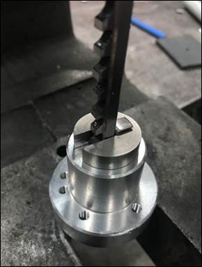
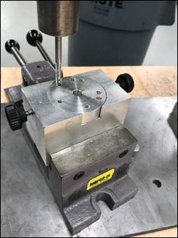
2.
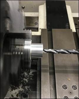
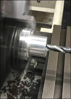
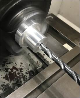
Zeroing
Blind Holes (e.g. Entstort Hub). To
properly zero a drill bit when creating a blind hole, ensure
you zero at the start of the full diameter (2nd and
3rd) of the drill and not on the tip or tapered
portion (1st).
To set the zero for a blind hole, drill slightly past
the tapered portion of the drill tip, retract the drill to the
position where the full diameter is in the plane of the face
of the part, and zero the Vernier dial on the axis hand-wheel.
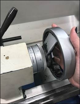
3.
Zeroing
/ Creating Blind Holes on the Mill. If you wish to
create a blind hole on the milling machine, there are two
common methods. The
first is to set the zero height using the spindle and to
adjust the depth stop using the ruler on the front of the
quill housing or a pair of calipers for more accurate depths. The second method is
to set the zero height using the spindle, adjust the depth
stop so it is in contact with the quill stop, retract the
quill, raise the table by the depth you wish to bore, and then
use the quill handle to bring the quill stop back into contact
with the depth stop.
INSERT PHOTOS SHOWING DEPTH STOP USED WITH INTERGRAL
RULER AND DEPTH STOP USED WITH CALIPERS TO SET DEPTH
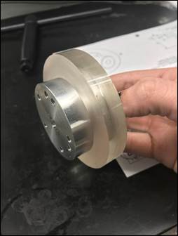
4.
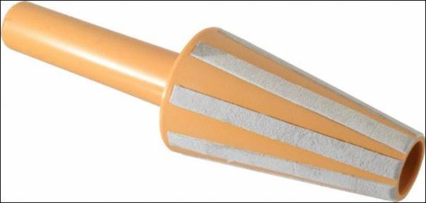
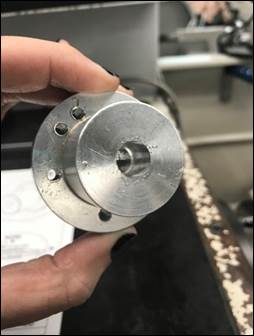
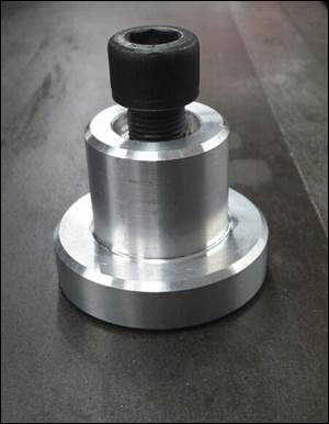
Polycarbonate
Disc for Entstort Hubs. If you have trouble
realigning the wheel hub in the lathe when creating the
counterbore in the Entstort hub use the polycarbonate disc on
the front shoulder and re-clamp in the lathe.
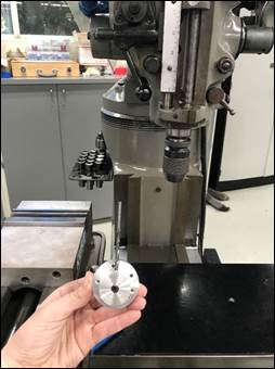
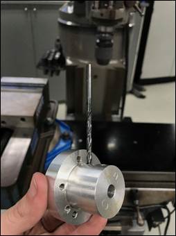
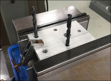
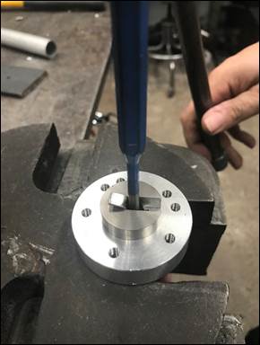
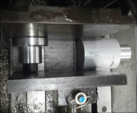
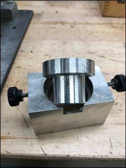
5.
Re-aligning
a Part (e.g. Wheel Hub Set Screws). If a student
unclamps a part and needs to reinstall it to tap the side
holes, it will need to be re-aligned vertically. An easy way to
re-clamp the part is to insert the proper size drill bit into
the existing hole, install the drill bit into the drill chuck,
lower the quill handle to mount the part into the vise, and
raise the quill handle to remove the drill bit.
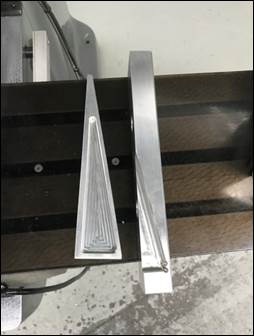
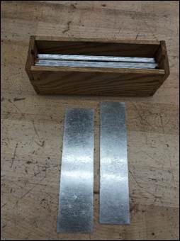
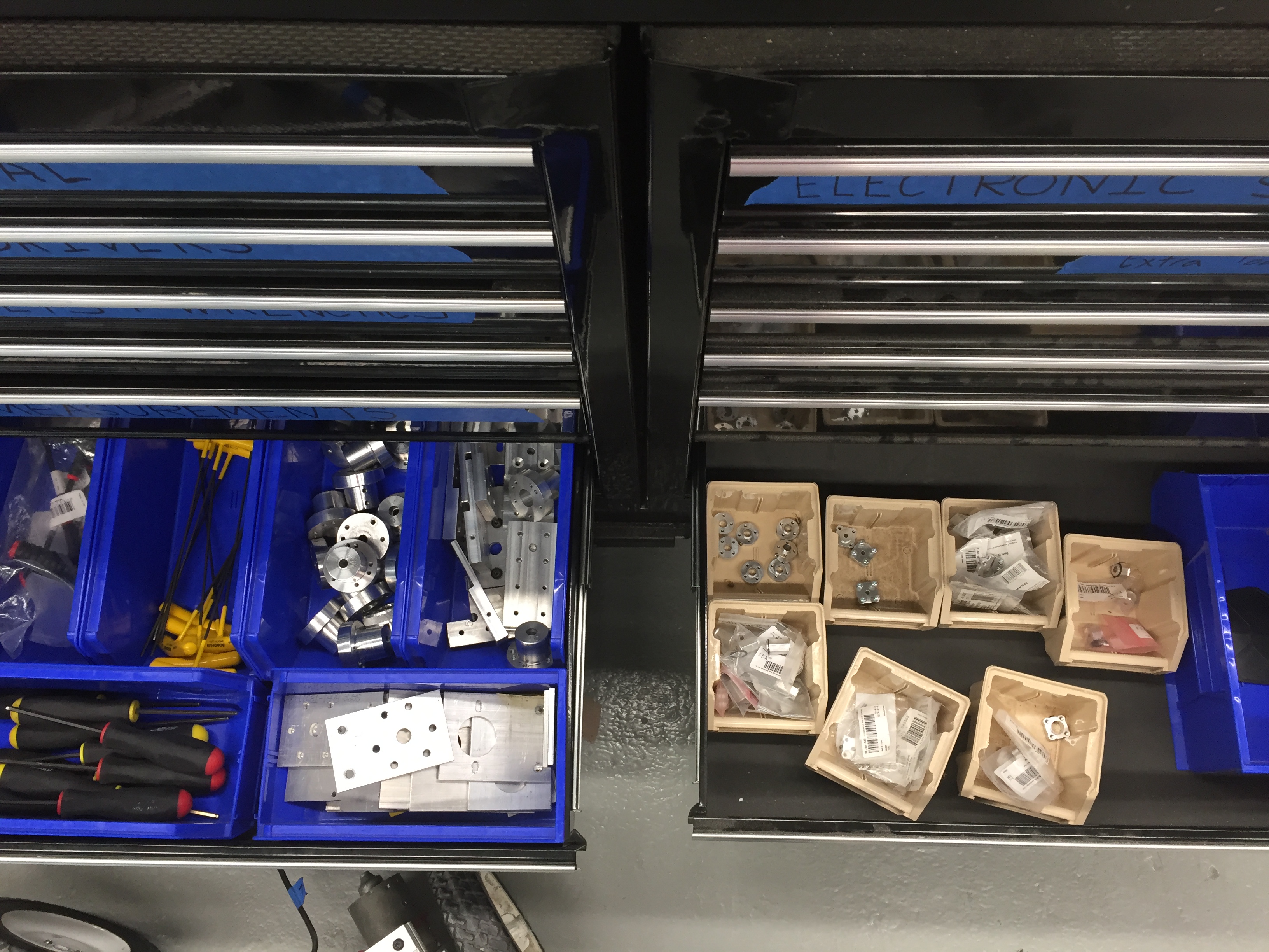
6.
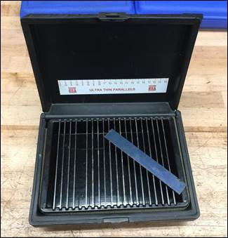
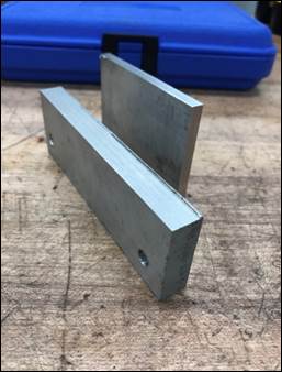
Ultrathin
Parallels. Sometimes we need to
leave parallels under parts so they don’t slip down into the
vise (when opposite sides are not very parallel or the part
can’t be clamped too tightly).
These two sets of 16 gage aluminum parallels are cut to
the heights needed to hold one or two 3/16” thick workpieces
for motor mount manufacturing.
There is also a full set of ultrathin steel parallels
in the left mill cabinet for other size workpieces. Notice the picture
showing the Kant Twist clamp used to clamp two identical motor
mounting brackets together.
These clamps are located in the mill table drawers, and
if used by students which don’t finish part manufacturing in
one work session, they should only be allowed to keep ONE
clamp on their parts until the following week’s lab (so we
don’t run out of clamps).
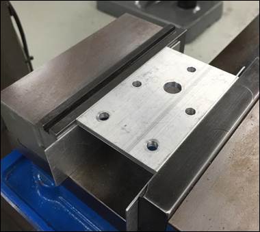
7.
Paint
Paddles.
When clamping a workpiece with non-parallel sides (anything
greater than 0.003” out of parallel) insert a paint paddle
against the moveable jaw to provide a complaint material on
which to clamp. We
also have ½ x 2” Delrin strips to use for the same purpose.
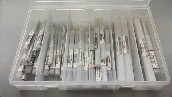
8.
Reamers
for Motor Shafts. We have reamers for
each size motor shaft listed in the Motor
Specifications
Sheets. These
reamers are stored in a clear labeled tackle box that sits on
top if the lathe cabinets during the prototyping phase of the
course. Be sure
to clean and return the reamers to their plastic storage tubes
and to the tackle box when finished using them so they do not
get lost.

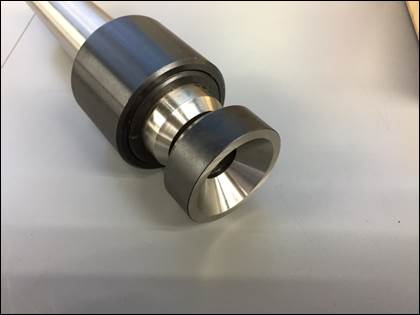
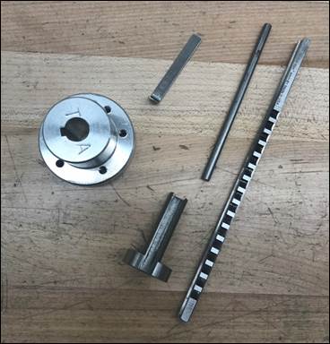
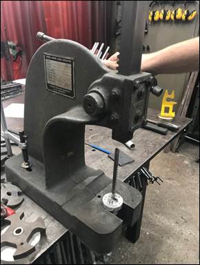
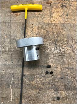
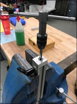
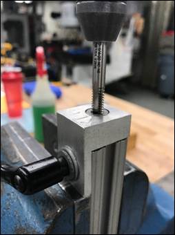
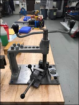
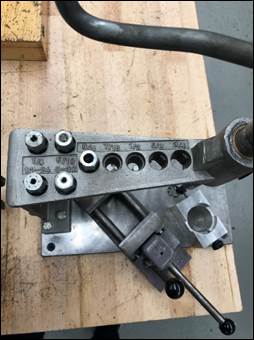
9.
Cytron Hub Broaching (link
to
part drawing). The wheel hubs
for the Cytron motors need
to be broached
to create the internal keyway used to transmit torque. The tools necessary
to produce the keyway include the broach, broach bushing,
shim, and ejection rod (1st), which are all stored
in the clear tackle box in the Motor Supplies drawer
of the black TA toolbox in the rear room. To make the first
broaching pass, insert the bushing and broach into the hub,
apply oil, and use the arbor press to gently push the broach
through the hub (2nd, 3rd). When doing this,
make sure the broach remains co-linear with the hub’s axis (simply stop and adjust the
arbor press ram if it does not).
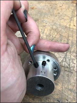
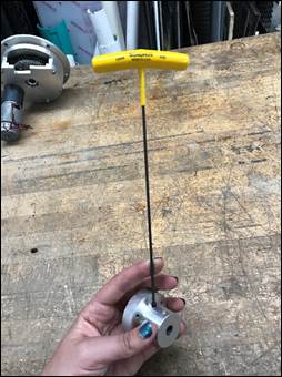
Next, repeat the process after adding the first shim
behind the broach to cut the keyway to its final depth (4th). Flip the hub over
and repeat the process using the shim (5th), or use
a second shim to increase the depth of the keyway so the hub
slides easily onto the motor shaft. Use the ejection rod
to advance the broach all the way through the part (6th). Be careful not to
drop the broach, as it is made from heat treated HSS, which is
very brittle and easily broken (as the student you are helping
to hold the broach before pushing it the remainder of the way
thru the hub using the ejection rod).
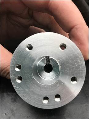
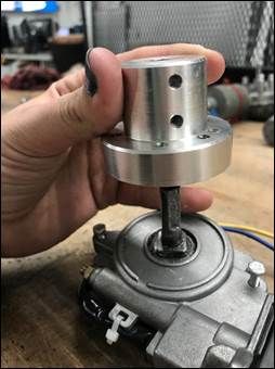
10. Cytron
Hub Modification. In some cases
the snap ring and shaft that protrude from the backside of the
wheel hub will interfere with the drive wheels. If that’s the case
or there’s another reason the motor shaft needs to be flush
with the face of the hub, simply counterbore the hub 0.1” deep
with a Ø0.75” endmill and place a few washers on the motor
shaft to offset the hub so it’s recessed with respect to the
face of the wheel hub.
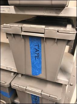
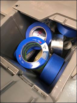
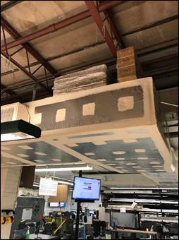
11. Common Prototyping Materials. Often
in office hours materials like
tape, hand tools, cutting supplies, cardboard, and a surface
to cut cardboard are necessary.
The tape is located on the rotisserie
in the main lab but may run out.
If this occurs grab a roll from the tape bin located on
the rack located by Aaron’s lab door. The common tools and
cutting supplies are located in the black TA toolbox in the
appropriately labelled drawer.
Above the air duct by the bathroom entrance is a stack
of extra cardboard, and to prevent damage to work table or
floor surfaces when cutting the cardboard use the 2’ x 4’
sections of plywood on the material rack next to the
refrigerator.
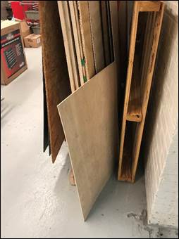
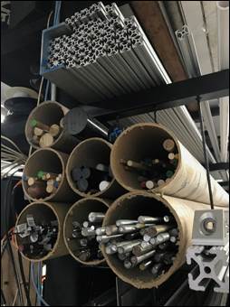
12. Small Diameter Round Stock. On
the left end of the main lab material rack are cardboard tubes
which hold various small size aluminum, plastic, steel, and
wood rods. There
is also a tube containing steel threaded rods.
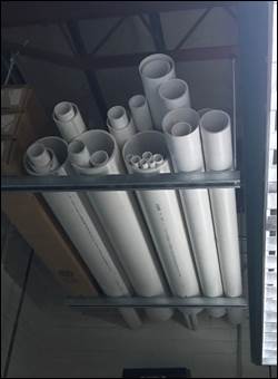
13. PVC Pipe. The
material rack for PVC pipe is located to the right of the CNC
lathe on the ceiling mounted rack. There is ladder
directly beneath to access the material.
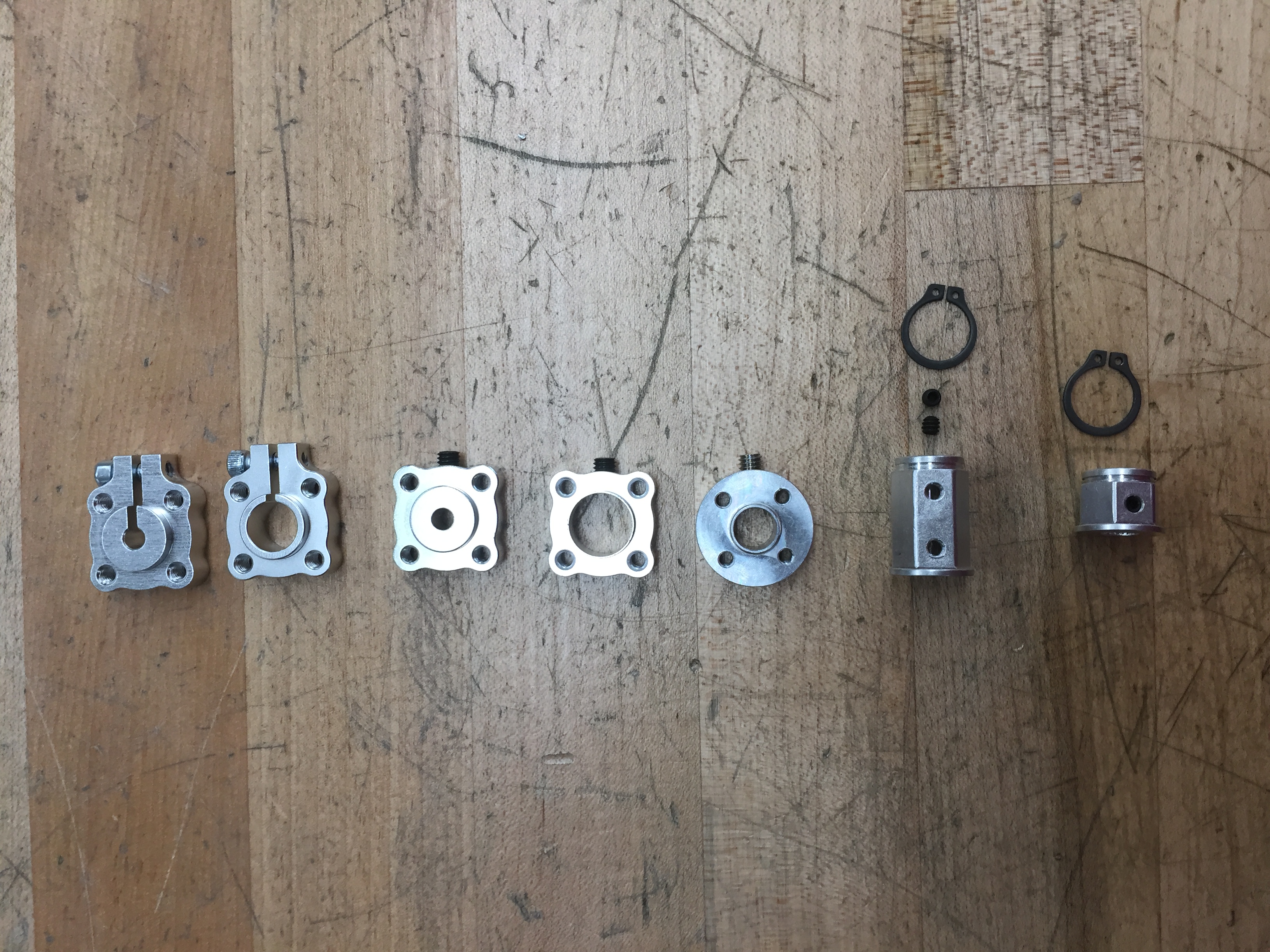
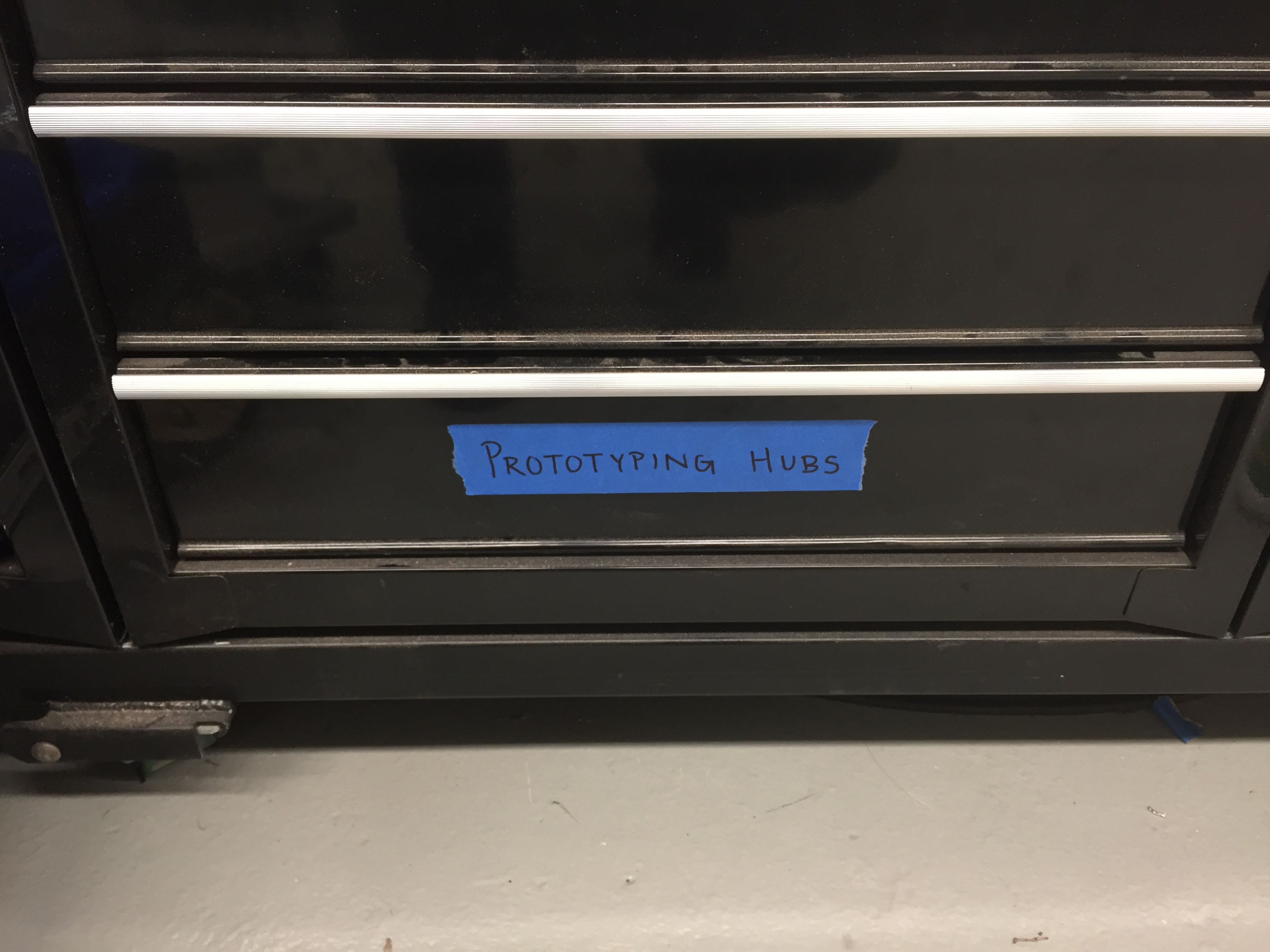
14. Motor Shaft Clamp Hubs. Students need these
when prototyping shooting-style mechanisms; they are located
in the black toolbox under the Abrams Table.
15. Small Wheels. Students
need these when prototyping shooting-style mechanisms for ping
pong balls; they are located on the rotisserie.
16. Helpful / Interesting Prototyping Examples.
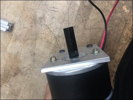
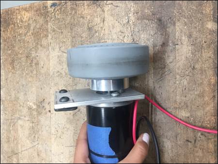
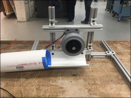
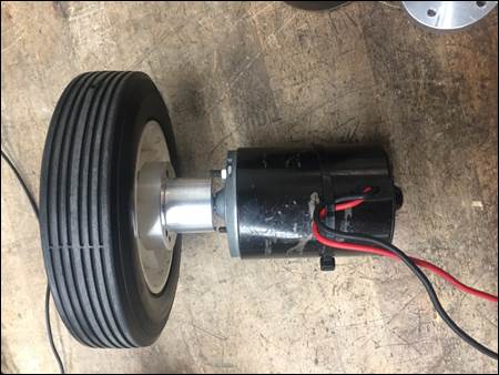
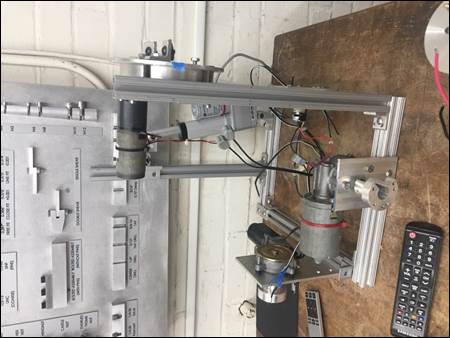
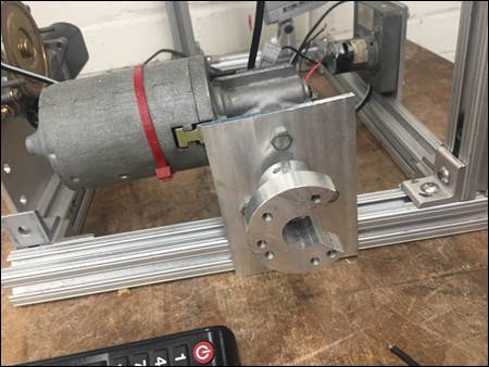
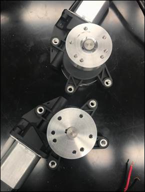
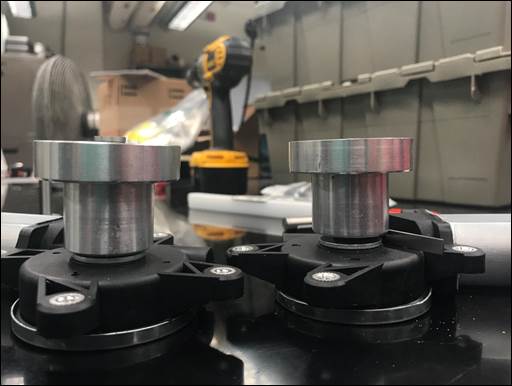
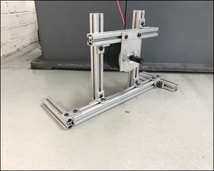
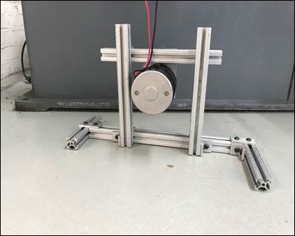
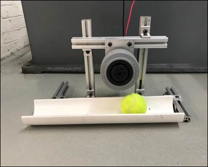
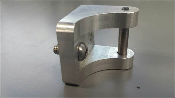
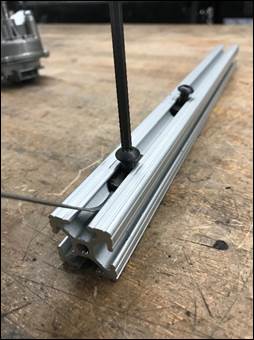
17. Flywheel
Testing / Mounting. If a student desires
to test a flywheel mechanism, do not allow students to hold
the motor by their hands for this will jeopardize the student. Grab the appropriate
wheel hub and motor mounts from the TA Miscellaneous or
Prototyping Hubs drawers.
Construct a sturdy motor mount out of 80/20 similar to
the one shown in the pictures.
This design can be adjusted to what the student needs. Take note it is
important to make the 80/20 that holds up the motor and motor
mount so its height is adjustable to allow students to gauge
the amount of pressure and clearance for a ball to pass
through. If there
are a lot of flywheel designs in office hours, attempt to
construct about 4 mounts with various motors and make students
sign up for testing each motor in designated safe areas.
Fasteners
[RETURN TO T.O.C.]
1.
Lab Fasteners Sizes. Become familiarize
with commonly available hardware in the lab and reference this
sheet with your groups as they select hardware. Any fasteners can be
ordered, but it’s more work for everyone.
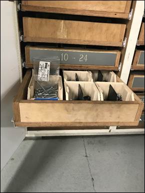
2.
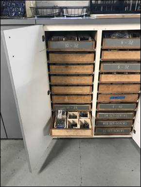
10-24
x 1-1/4” Fasteners. 10-24 x 2-1/4”
fasteners are required for the metal hub 8” drive wheels
available in lab. These
fasteners are in the cabinet with all the other non-standard
10-24 hardware.
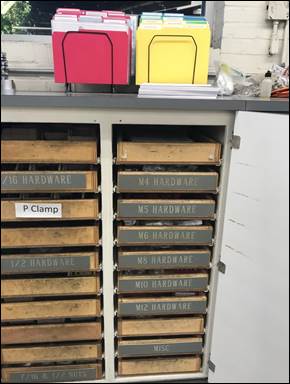
3.
Metric
Fasteners. The metric fasteners
stocked in lab are found in the lathe cabinets under the TA
folder racks.
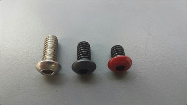
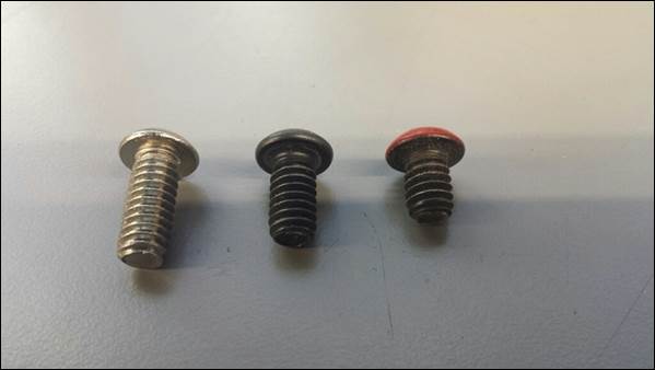
4.
¼-20
Button Head Cap Screws. There are three main
lengths of button head cap screws used in the lab: 5/8”, 1/2",
and 3/8”. ¼-20 x
5/8” BHCS fasteners are used to attach the OTS linear actuator
mounting brackets to 80/20 extrusions, are silver in color for
easy identication, and are found
in the ¼” hardware drawer in the fasteners cabinet by the
lathes. ¼-20 x
1/2” BHCS fasteners are the standard fasteners used with the
80/20 extrusions, are black in color, and are located in the
rotisserie. ¼-20
x 3/8” BHCS fasteners are used to attach thinner parts like
sheetmetal to 80/20 extrusions, are black with a painted red
head for easy identification, and are also found in the
rotisserie.
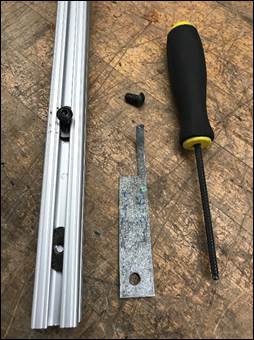
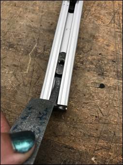
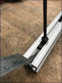
5.
80/20
T-Nut Tool. When assembling 80/20
with the ¼-20 BHCS and t-nuts, often the tee nuts will not
immediate tighten due to the fastener not grabbing onto the
threads. On the rack with the TA safety glasses there is a
piece a sheetmetal bent and cut to shape. To use place bent
end under the edge of the t-nut in the 80/20 channel and push
down lightly this should lift the t-nut enough for the BHCS to
grab and be properly tighten down.
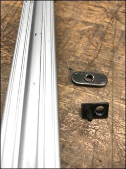
6.
Roll
In T-Nut. These
T-nuts are only to be used in the last week of manufacturing
and testing! These roll in
t-nuts are located in the Misc. Supplies drawer in the black
TA toolbox, these t-nuts allow the user to use the curved of
the t-nuts and roll it against the channel in the 80/20 rather
than sliding from the end. This is useful due to the fact that
this type of t-nuts does not require the 80/20 to be
disassembled to add additional t-nuts.
Project Motors and Miscellaneous
[RETURN
TO T.O.C.]
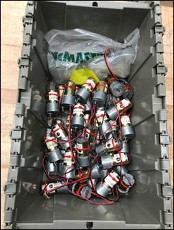
1.
Motor Specifications
Sheets. Be familiar with the
different motors available in lab so you can made helpful
recommendations to the students.
2.
Motor
respect. As lab instructors and
protectors, there are several things we must do to ensure the
motors are respected:
a.
Do
not allow students to overload a cantilevered motor with an
excessive overturning moment (it should
never exceed the rated torque output of the motor); if it
does, it needs to be redesigned to have a support so it’s no
longer cantilevered, or to use a larger motor.
b.
Require
students to use ALL provided mounting holes when designing
motor mounts. The only exception
that comes to mind is mounting the Globe motor to an 80/20
frame member, which has never caused an issue because the
Globe motor housings are manufactured from high strength
6061-T6 aluminum versus the cheaper, weaker cast metals from
which all the other motor housings are made.
c.
Be
very cautious of the fragile motor wires and fastener
threads. The wires entering a
motor’s casing are easily broken if pulled on or bent tightly,
and once broken they cannot be repaired. Similarly, threads
in the motor housing are weak to begin with, so it is
imperative to use the proper fasteners specified on the
motor’s spec sheet. A simple rule of thumb
to prevent fastener damage is to always ensure the mounting
fasteners can be screwed together completely by hand before
using a tool to apply the final tightening torque.
d.
All
motors except Densos should
have zip tie strain reliefs to prevent wires from pulling
out of their housings when accidentally pulled on.
e.
Never
give a motor to a group without testing it in front of the
students (which includes checking each threaded hole) and
making an appropriate note on their weekly progress sheet.
3.
Repairing
motor threads. When repairing
threads it’s
always best to use thread rolling / forming tap as opposed
to a normal thread cutting tap,
as the former pushes the remaining threads back into their
proper position, as opposed to a cutting tap, which cuts away
more of the damaged thread material, leaving behind an even
weaker thread. I
elaborate on thread repair here.
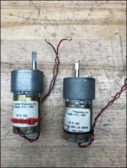
4.
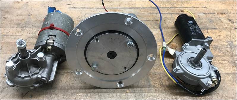
Buehler
Motors. In lab we have two types of
Buehler available for students to use. The difference
between the two types is the mounting hardware: one type uses
M3 fasteners while other uses standard 6-32 fasteners. To quickly
distinguish between the metric and standard Buehler motors the
strain relief zip ties are different colors. The red zip tie
denotes the metric type and the black zip tie denotes the
standard type. The
majority of our supply of Buehler motors are metric, so the
few standard types have been pulled from the shelf and put
away in one of the grey storage bins located by the student
workstations. When
selecting the appropriate hardware, always be sure to check
that the fasteners thread into each mounting hole by hand.
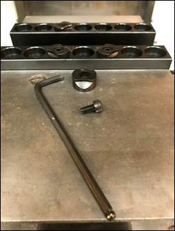
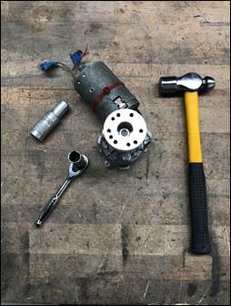
5.
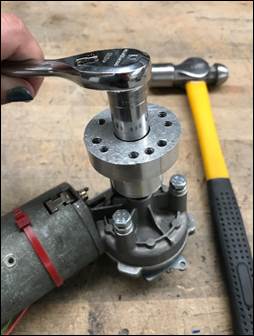
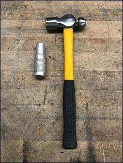
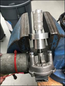
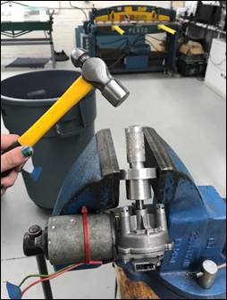
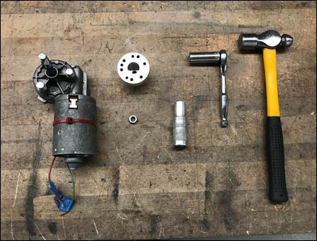
Entstort
Hub Removal. The
Entstort wheel hub requires a specialized punch to remove the
aluminum wheel hub from the motor shaft due to the splines on
the motor shaft. Located in the punch drawer of the red tool
box is the Entstort hub punch. Prior to using the punch remove
the M8 nut from the end of the motor shaft with a 13 MM deep
socket. Clamp the wheel hub into a vise, load punch into the
wheel hub counterbore and firmly tap the punch to separate the
hub and motor shaft.
7.
Motor
Fasteners. At
the end of the semester there are three motors in which we
leave the motor fasteners to ensure that at the beginning of
the following semester in order to minimize damage to motor
threads. Reminder: making sure as a
TA to supply your groups with the proper mounting hardware
for all motors. Denso, Entstort, and Globe motors
should all retain their fasteners after competition. For the
Denso the M4 x 0.7 fasteners in each of the three flanges
should stay and when reinstalled the addition of Delrin
spacers should be added to prevent damage to the flanges. In
the Globe motor face (2) M6 x 1.0 are required and in the
Entstort should have three M6 x 1.0 fasteners and the motor
shaft should have an M8 nut.
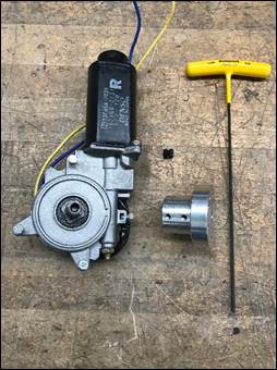
8.
Denso
Set Screws. A common occurrence
when using the Denso motors is to have the set screws slip off
the motor shaft. Always
make sure the flat on the motor shaft is aligned with the set
screw holes. To
minimize this risk of the set screws slipping, clean the oil
remaining on the wheel hub using Simple Green and a cotton
swab located in the cleaning supplies cabinet, tighten a
second set screw down against the first one, and tighten down
the set screws using the long yellow handle Allen wrenches
found in the bottom of drawer of the black TA tool box.

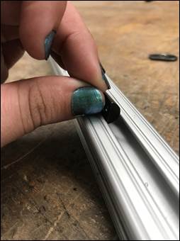
9.
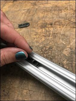
80-20
T-Nuts. Did you know the
regular 80-20 tee nuts are directional? The threaded
protrusion should always face downwards, away from the slotted
portion of the extrusion.
Control Boxes
and Electrical [RETURN
TO T.O.C.]
1.
Robot Testing
Procedures. Be familiar with and
follow the robot testing procedures.
2.
Battery
Connections. Be very gentle with
the battery connections and make sure you always pull on the
plastic connector bodies, NEVER on the wires themselves, or
you will break the fragile solder joints.
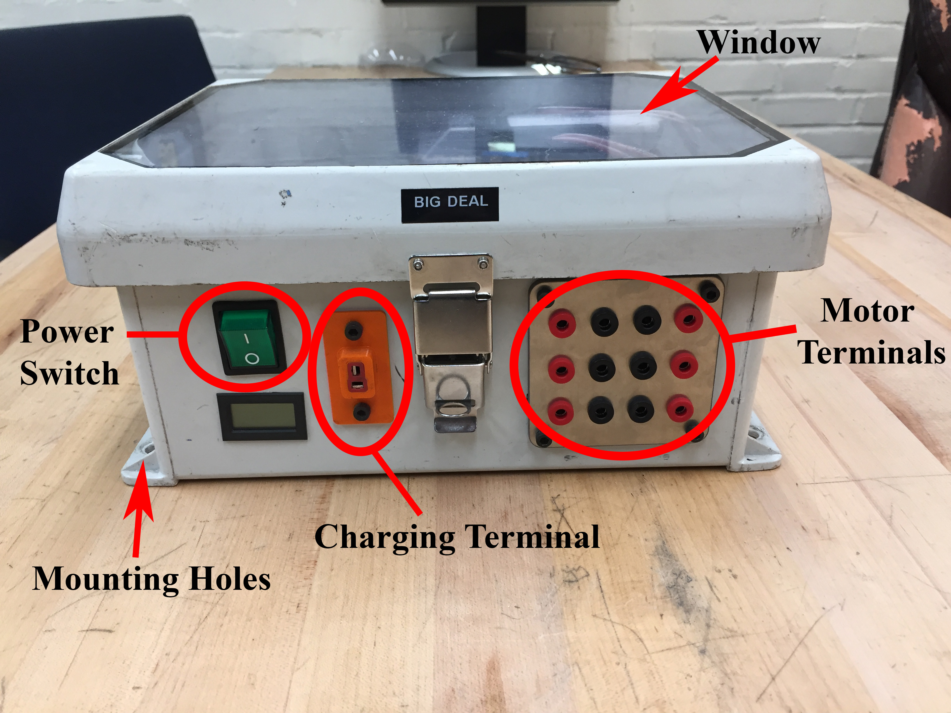
3.
Motor
Connection Terminals. The spring loaded
banana clip connection terminals on the control box are
extremely robust and should present no problems when inserting
or removing the mating WEGO terminals.
4.
Wire
Routing and Securing. Wires must always be
properly routed and secured.
Whenever possible, avoid routing wires in areas where
there is movement (such as close to wheels and mechanisms that
move). Never let
wires hang in free space; always use tape (cheapest) or zip
ties (looks nicer, but is much more expensive) to secure wires
so they don’t move and loosen when the robot is in motion.
5.
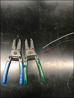
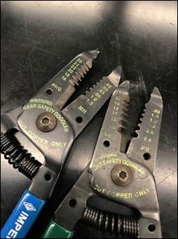
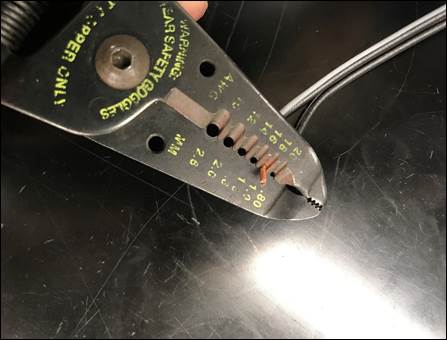
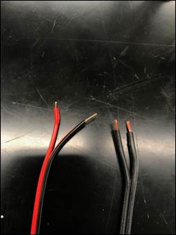
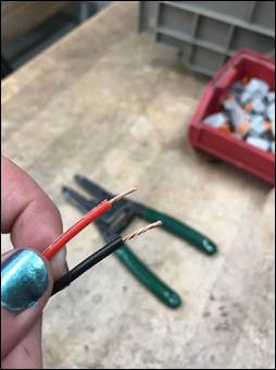
Wire
Stripping. Wire strippers are used to
cut and strip wires on electrical components like motors or
wire extensions. If
you know the wire gauge then select the labelled slot, cut
through the insulation, and pull it off the end of the wire. If you don’t know
the gauge of the wire, select the largest labelled slot on the
strippers, and if the insulation doesn’t slide off then move
to the next smaller size until it does. ALWAYS avoid cutting
the copper strands; if there are cut strands the selected slot
/ wire gauge was too small.
The base of the internal jaws contains a pair of wire
cutters for trimming the wire to length or cutting off a
damaged section.
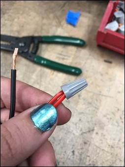
6.
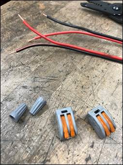
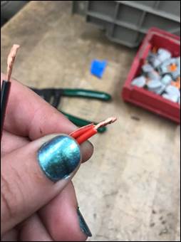
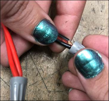
Wire
Nuts. To
extend motor wires use wire nuts or WEGO connectors, after
stripping the wire twist the copper strands clockwise (follow
right hand rule) then twist the two wires together and screw
the wire nut down on to the set of twisted wires, tug slightly
on the wire nut to ensure its attached.
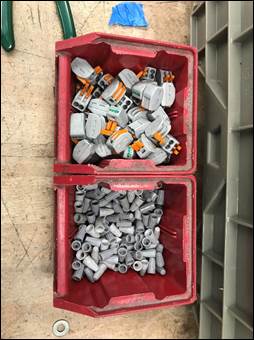
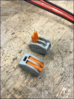
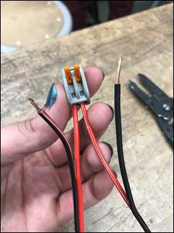
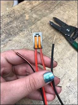
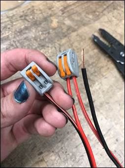
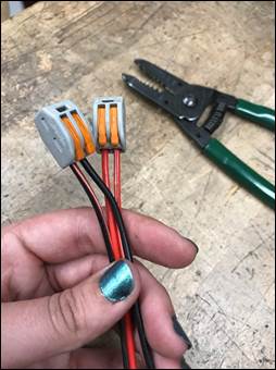
7.
WEGO
Connectors. An alternative to wire
nuts are WEGO connectors.
To use, open the orange prongs (this will require some
force), make sure the copper strands on the extension wires
are properly twisted, insert the appropriate end into the
connector, and the snap the connector closed. Caution:
when snapping the connector shut be careful not to pinch
your fingers in the orange prongs!
8.
Introduction
to Soldering.
a.
Here
is a short video on the basics of soldering, including how
to prepare the iron to start soldering. Note that most of
the soldering required in lab will only be wire splices.
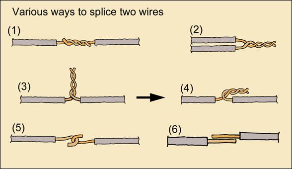
b.
Types
of Wire Joints. There are multiple ways to
join wires depending on the gauge and length of wire being
used. Splice the
wires together and properly tin then place a piece of heat
shrink around the connection.
The first style (1) is called Inline Splicing and is
very common. Here’s
link to a nice
tutorial describing the process with photos.
Bandsaws
[RETURN TO T.O.C.]
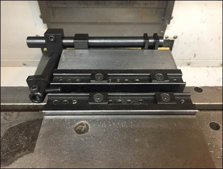
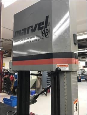
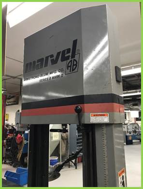
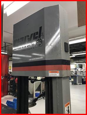
1. Using
Marvel Vise. This is not trivial, so please pay
attention to what you are about to read. The Marvel vise has
two halves: a left and a right.
Always clamp both halves of the Marvel vise, as doing
so mitigates the chance of circular workpieces spinning in the
vise and destroying the blade.
When necessary, use material drops off the rack to span
the gap between the second pair of vise jaws. Make sure the vise
handles are properly tightened to prevent part slippage and
blade damage during cutting.
If the part being clamped is less than half the width
of one of the jaw halves, and adjust and use the provided
machinist jack (photo 3) to act as an identical thickness
spacer to prevent a bending moment from being applied to the
vise jaw (photo 4). When cutting round material, the blade
force must be reduced by at least 50% so as to not cause the
work to rotate in the vise.
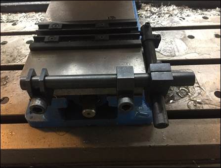
2. Adjusting
Marvel Vise. The Marvel vise can
be adjusted to cut wider parts by loosening the ½” bolt on the
top, sliding the moveable jaw rearward, and re-torquing the bolt. When finished,
please return the vise to the original position for use
cutting normal lab stock.
The ratchet and socket for adjustment should be stored
on the machine. Be
sure to clean any debris out of the ½” Allen screw before
attempting to loosen.
INSERT PHOTOS SHOWING MARVEL VISE
TOP BOLT BEING LOOSENED AND A LARGER PIECE OF STOCK CLAMPED IN
THE VISE
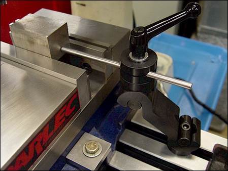
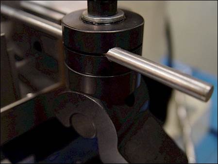
3.
Marvel
Blade Guide. When adjusting the
upper blade guide on the Marvel, NEVER loosen the tension
handle / knob more than 1/4 of a turn, as doing so can cause
the upper guide assembly to come off its guide track, in turn
causing the blade to come off its guide.
4.
Workpiece
Clamping Orientation. When cutting parts
in the bandsaw, it is typically advisable to orient parts so
the cross-sectional cutting area remains as constant as
possible throughout the cut and so the parts engage the
largest number of teeth on the blade. These points are
illustrated in the following image.

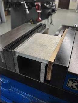
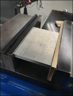
5.
Clamping
Multiple Parts. It is often helpful
to clamp/cut multiple pieces of (non-circular) material in the
Marvel or Roll-In bandsaws at the same time (such as 80/20
extrusion). When
doing this, it’s important to clamp the parts horizontally in
the bandsaw vise, NOT VERTICALLY; this ensures each part will
be clamped securely, even if they aren’t all the exact same
thickness.
Common Tooling
[RETURN TO T.O.C.]
1.
Common Drill Sizes. Familiarize yourself
with commonly available drill sizes so you can help your
students design accordingly.
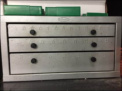
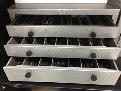
2.
Drill
Index Refills. In the far left gray metal
cabinet behind the mills are Huot
cabinets containing refills for the drill indexes located by
the mills and lathes. If
you need to replace a missing or damaged drill simply looked
for the appropriately labeled drawer and select the desired
drill (standard or metric).
Please let the lab director know if quantities run low
(<12 on drills ¼” and smaller, and <6 on drills larger
than ¼”).
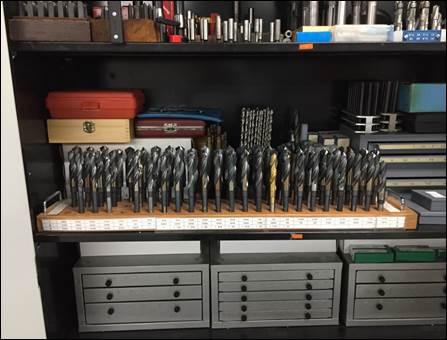
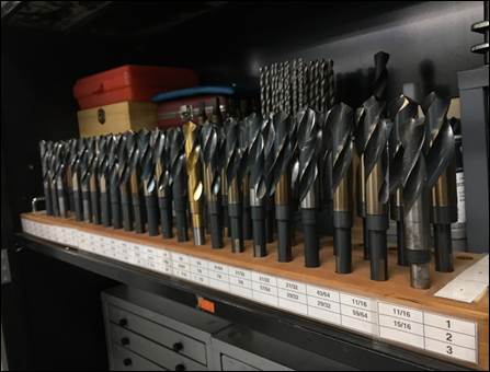
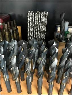
3.
Reduced
Shank (Silver & Deming) Drills. In the left gray
metal cabinet behind the mills are reduced shank drills that
are only used in ½” collets in the mills to drill holes
ranging in size from 33/64” to 1-1/2”. Never clamp these
drills in drill chucks, as doing so will damage the precision
shanks unless they have 3 flat ground into them 120-deg apart.
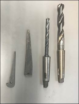
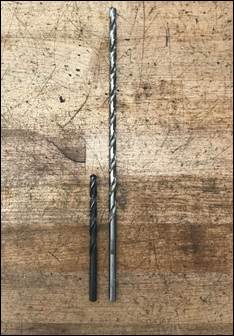
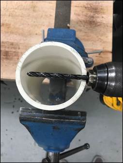
4.
Aircraft
Drills. Aircraft drills are
extra-long drill bits. They
are located in the third (from the lab door) grey metal
tooling cabinet. A common use
for aircraft drills in lab is placing thru holes in PVC pipe. In the photo below
we started with a 1/4” drill through the first side (center)
followed by a 1/4” aircraft length drill (right) which (unlike
the standard jobber drill) reaches through the entire PVC
pipe.
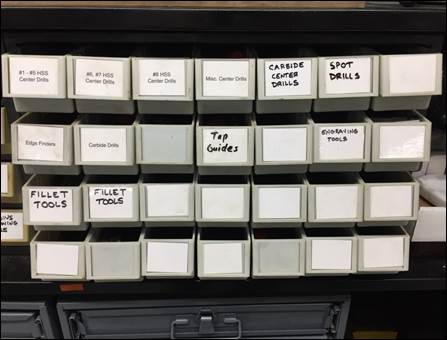
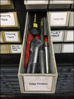
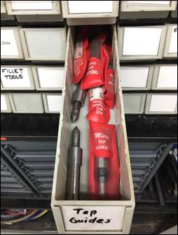
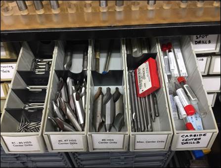
5.
Extra
Center Drills, Edge Finders, and Tap Guides. In the middle grey metal cabinet behind the
milling machines are small white drawers labelled with extra
machining tools. Some
of these tools you may have only encountered the most common
size located out on the milling machine table, however there
are several more sizes and styles of tap guides and center
drills for smaller and larger applications. Some of the
smaller center drills may be helpful for smaller sized drills
or taps.
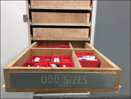
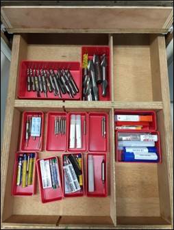
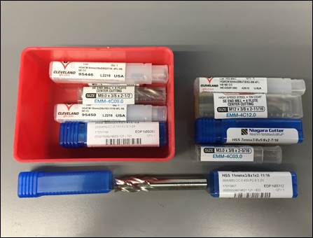
6.
Metric
Endmills with Imperial Shanks.
In
the first wooden cabinet (from the lab door) on the left hand
side under the drawer labelled “Odd Sizes” is an assortment of
metric sized endmills with imperial (inch) sized shanks (!)
that are compatible with the standard R8 collets located on
the milling machines. Using
normal metric endmills (with metric shanks) would require
special metric collets, which would create a lot of confusion
(and carnage) in the lab.
Threading
[RETURN TO T.O.C.]
1.
Five
threads of engagement. As explained in the
lecture
notes
on fasteners and threading, a MINIMUM of five full
threads of engagement are required to achieve full fastener
strength.
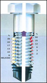
To
calculate the minimum part thickness necessary to achieve the
required five threads of engagement, multiply the thread pitch
of the fastener by five.
For example, if we desire to thread a workpiece for a
10-24 UNC fastener, we would require a minimum part thickness
of 5 threads × (1 / 24
in/thread) = 0.208″.
Or if we desire to thread a workpiece for an M6x1.0
fastener, we would require a minimum part thickness of 5 threads × (1.0
mm/thread) = 5mm ≈ 0.197″.
2.
Broken
tap extraction. You will see many
widgets marketed as tap extractors, but they are all lies J. If you break off a
tap and cannot remove it with a pair of vice grip pliers, toss
the part in the trash or pay someone with an EDM to remove it. Quality taps are
made of HSS, which is of equal hardness to HSS drills,
therefore brittle carbide drills are required, but drilling
the tap is usually an interrupted style cut, so the only thing
that’s certain is that it’s going to end badly
J.
3.
Braddock’s
Broken Rule. When you know
something is broken, PLEASE ASK before trying to fix it, as
trying to fix a failed fix rarely ends well, and two heads are
usually more successful than one!
4.
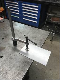
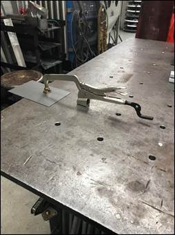
Tapping
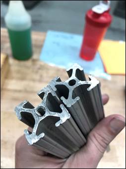
80/20. Not coincidentally, the
extruded hole thru the center of each 1” 80/20 extrusion
measures Ø0.201”, which is the tap drill size for a 1/4-20
fastener. A
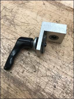
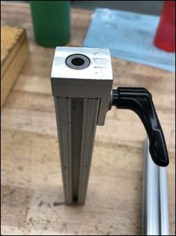
simple way to tap the end of a piece of 80/20 is to use the
jig located in the mill table tackle box. The jig attaches to
the end of the extrusion using a tee nut and quick clamp
handle. Attach
the jig, clamp the 80/20 in a vice and use a 1/4-20 UNC tap
with cutting oil to produce the threads.
5.
Tapping
station. The
tapping station is used to quickly thread workpiece that have
already been tapped drilled.
Hex-shaped holders contain labeled taps ranging from #8
to 1/2”. There is
a small vise with the tapping station that allows smaller
parts to be securely mounted and a pin that can be placed in
several holes in the base to brace the vise against rotation. The hex-shaped tap
holders quickly snap in and out of the T-handle, which ensures
holes are tapped normal to the table surface. There is also a
rectangular block for use tapping the holes in the face of the
wheel hubs (which takes about 15 seconds per hole).
Welding Shop [RETURN TO T.O.C.]
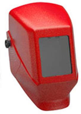
1.
Welding
Helmets. We have four styles
of welding helmets and it’s important to understand the pros
and cons of each. Let’s
start with a discussion of the different lens shades available
in modern welding helmets.
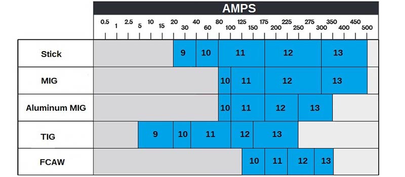
As seen in the following chart, higher number lens
shade numbers correlate to darker tinted glass. Since most laboratory MIG and TIG welding takes
place between 60 and 150 amps, a #10 shade lens is ideal for
most uses. When
TIG welding thinner materials at lower amperage settings, a #9
shade lens would work well, and when welding thicker materials
(which is rare) a #11 or #12 lens would be appropriate. These helmets should
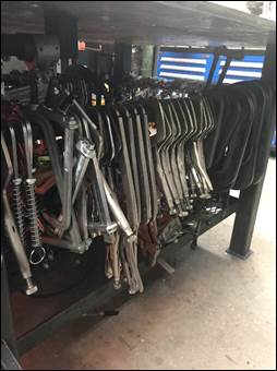
always be put away on the hooks on the north wall of the
welding shop. If
during use you notice any problems with the helmets (dead
batteries, scratched lenses, broken headgear, etc.), please
bring the helmet to the office so it can be repaired or
replaced. When
cleaning the plastic lenses, always use a damp clean paper
towel from the restroom.
a.
Jackson Passive Helmets. These are the red /
maroon helmets that have a fixed, passive #10 shade lens. These work well, but
the headgear is not very durable, so we keep them around as
backup units in case the more complex and expensive helmets
fail. These
helmets cost about $60 each.

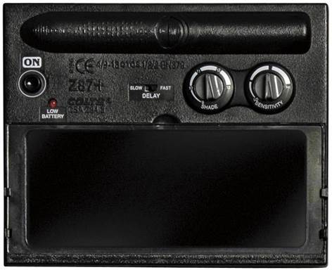
b.
Miller Classic Series Variable Shade (#8-12)
Auto Darkening Helmets. These are our new
“go-to” helmets for normal MIG welding and welding demos. The delay (how long
the lens takes to return back to the unshaded state after the
welding arc ceases) should be set to slow and the shade should
be set to #10. You
must press the ON button before using this helmet. These helmets cost
about $90 each.

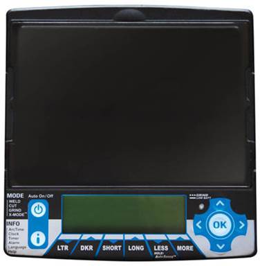
c.
Miller Elite Auto Darkening Helmets. These are our new
go-to helmets for normal TIG welding and should only be used
by TAs. The delay (how long
the lens takes to return back to the unshaded state after the
welding arc ceases) should be set to slow and the shade should
be set to #10. You
must press the ON button before using this helmet. These helmets cost
about $220 each.


d.
Miller Infinity Auto Darkening Helmets. These are our
flagship helmets for TIG welding and should only be used by TAs. The delay (how long
the lens takes to return back to the unshaded state after the
welding arc ceases) should be set to slow and the shade should
be set to #10. You
must press the ON button before using this helmet. These helmets cost
about $260 each. If
you can’t weld well using this helmet, it’s time to return to
machining :).

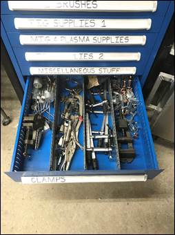
2.
Welding
Shop Clamps. Around the welding
table and in the right-most welding shop toolbox is a
collection of clamps to securely clamp parts.

a.
F-Clamps / Bar Clamps. F-Clamps
are simply quick acting C-clamps which are used to parts to
each other or directly to the welding table.


b.
Table Clamps. Table
clamps come in different styles and use 5/8” holes in the
welding table to clamp workpieces directly to the table for
welding. If you
haven’t used them, try them, because they work really well and
allow you to clamp parts anywhere on top of the table, versus
only around the table’s perimeter using conventional clamps. The table clamps are
located in the lower drawer of the right-most toolbox.
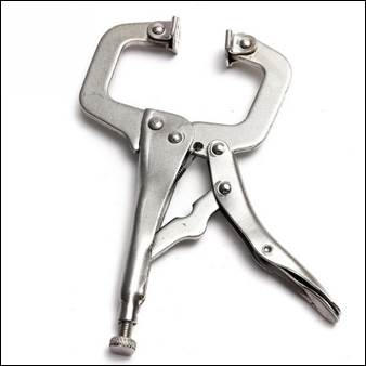
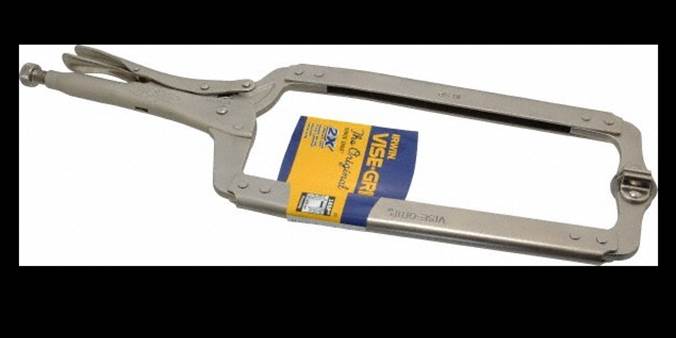
c.
Vise Grip Clamps. Vise
grip style clamps exist because of their convenience of use. Used properly, they
work well. Used
improperly, they offer the least robust method of clamping,
but work fine for general purpose work-clamping; however, they
should not be used for work involving grinders, since an
insecure clamping method could result in an injury.
3.
Welding
Shop Toolboxes. These toolboxes
contain all the tools you need when working in the welding
shop.
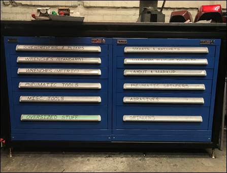
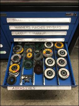

a.
Pneumatic Tools. Pneumatic
tools encompass all the tools in the shop which are powered
through compressed air. The
most commonly used pneumatic tool in the lab is the cut-off
wheel which is used to create slots and square features in
PVC. These tools
can be found in the fourth drawer on the left hand side of the
welding shop toolbox.
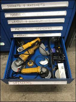
b.
Grinders.
There
are angle grinders located in the bottom drawer of the welding
shop tool box with replacement grinding, sanding, and cutoff
wheels in the drawer above them.
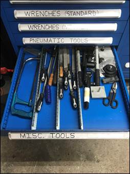
c.
Hacksaws.
More
useful tool are the hacksaws located in the Misc. Tools
drawer. These can
be used to cut through a variety of materials ranging from PVC
to metals.
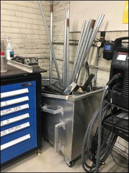
4.
Metals
Dumpster. All metal scrap should be
disposed of into the metals dumpster located in the back right
hand corner of the welding shop.
5.
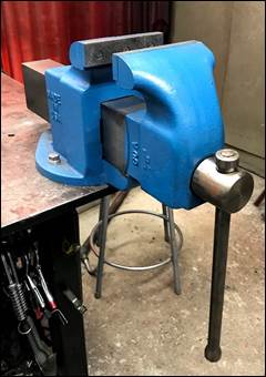
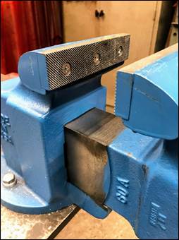
Heavy
Duty Bench Vise. Mounted to the corner of the
welding table is a large bench vise. Notice this vise has
serrated jaws that increases the clamping security of parts
clamped within, but also mars the surface of your workpiece. If planning on using
this vise either ensure that your surface finish is not
critical or add a shim (a piece of sheetmetal) between the jaw
and the workpiece to prevent marring.
a.
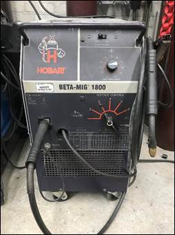
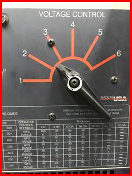
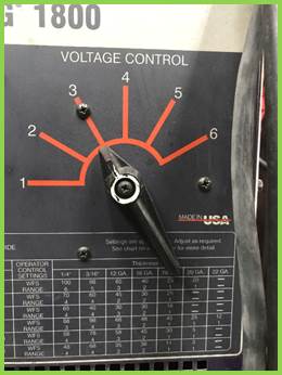
Power Level Settings. The
power (voltage) level is used to adjust for welding different
thickness materials. Setting
2 is used for steel sheetmetal, setting 3 is used for 1/8”
steel (i.e. the welding demos), and setting 5 is used for ¼”
steel. When tack
welding pieces together, always adjust the welder to one
voltage setting higher than you would for normal welding (i.e.
use setting 4 when tack welding 1/8” flatbars
together for the welding demos, but adjust the machine back to
setting 3 before performing the actual welding).

b.
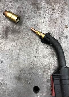
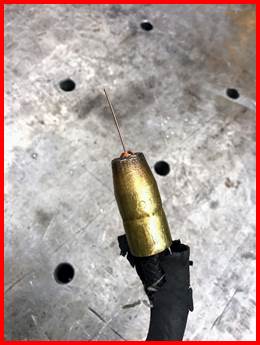
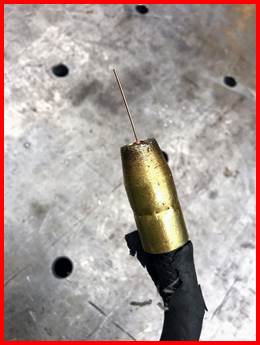
Gun Nozzle. The nozzle on the end of the MIG welder has the
potential the slide back exposing the internal collet from
which the filler wire feeders from, when this occurs the slag
from the welding process will build up between the collet and
nozzle cause the filler wire to join the nozzle and collet
preventing the wire spool from feeder the filler wire and
prevents MIG welding from working. To prevent this from
happening make sure to clean the nozzle and that the nozzle
extends approximately 1/16” past the internal collet. The
nozzle often shifts back when the nozzle is positioned into
the corner of a workpiece with force. This nozzle can be
adjusted by pulling on it, make sure that you use a pair
gloves if repositioning follow a weld as the nozzle may be hot
to the touch.
c.
Gas Level. When the regulator reads less than 1000 PSI the
tank is getting low make sure that gas has been reordered or
there are additional tanks available for the MIG (Argon – CO2
Blend) and TIG (Argon) welder.
d.
Wire Spool. When using the MIG welder check the status of the
wire spool located under the flap on the left side of the
machine, and notify Mike when the spool appears low enough to
be replaced.
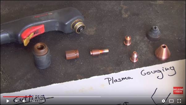
a.
Set-Up. When clamping
workpieces prior to plasma cutting ensure the portion getting
cut does not intersect with the table, or the plasma cutting
will cut in to the welding table and damage the surface.

b.
Templates.
When
possible, always take the extra minute to use a straight or
circle cutting template with the plasma, as the cut produced
will be of MUCH higher quality.
INCLUDE
PHOTOS SHOWING A STRAIGHT EDGE TEMPLATE AND A CIRCLE TEMPLATE
8.
Spot
Welder. The spot welder does
not work on aluminum workpieces!
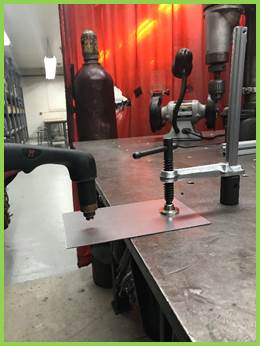
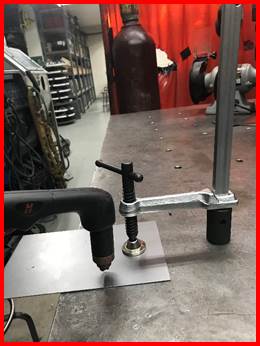
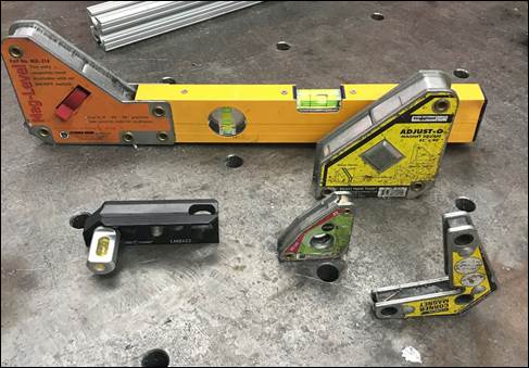
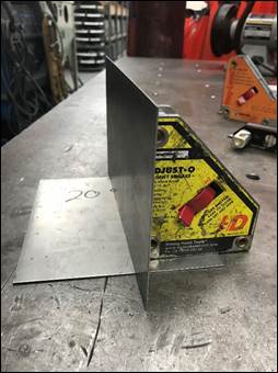
9.
Magnetic
Clamps. The
magnetic clamps are found along the edge of the welding table
or on the side of the hydraulic press. There are various size,
shape, and angle magnets to help set up parts for welding part
set-up, some of the magnets have the ability to turn on and
off using the switch on the side. There are also magnetic
levels that can be used to align parts. Occasionally, magnets
will be difficult to remove from the surface of the workpiece
push the magnet over 90 degrees (forcing the magnetic surface
away from the part) and pull magnet away. Warning: If using
while TIG welding the arc will not like being around the
magnet and jump away or not behave as normal due to the
interaction between the magnet and AC current.
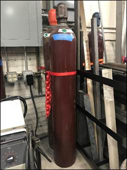
10. Welding Tank Safety. All
tanks that are not secured to a welder need to always be
secured using a chain, or strap to prevent the tanks from
falling over. The
tanks should always be labeled (there are magnets with labels
noting when the tank is empty), and when not attached to a
regulator should always have a cap. Handle empty
cylinders with the same care as full cylinders.
11. Removing Welds.
The
4-1/2″ angle grinder or the plasma cutter can be used to
remove spot welds and bead welds from student parts which have
be improperly or incorrectly welded.

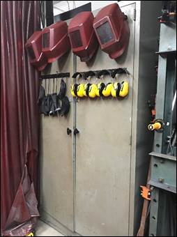
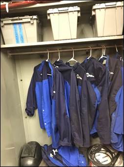
12. PPE Cabinet. In
the corner of the welding shop is a cabinet that contains the
protective gear required for welding in the lab, this includes
helmets, plasma cutting glasses, ear protection, and welding
jackets. When preforming tasks in the welding shop make sure
to use the appropriate safety gear and return it to the proper
location after use.
13. TIG Welding. Attach documents here!
Sheetmetal Equipment
[RETURN TO T.O.C.]
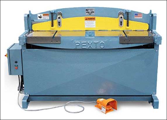
1.
Hydraulic Shear Safety. Always wear gloves when operating the
hydraulic shear because it is impossible for your hands to
come into contact with the moving blade. This
does not violate our normal gloves safety rule, since there is
nothing on which your gloves can catch and pull your hand into
the danger zone (as there is on a bandsaw, drill press, lathe,
or milling machine).
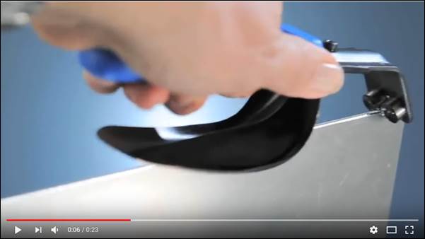
2.
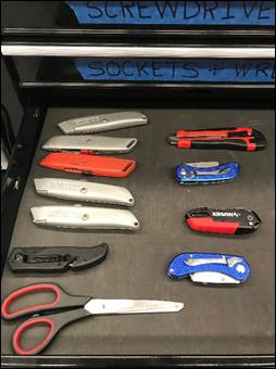
Deburring Tools / Techniques. As you know,
sheetmetal is extremely sharp until it has been deburred. The easiest way to
debur sheetmetal is to use the Noga
deburring tool shown in the following video.
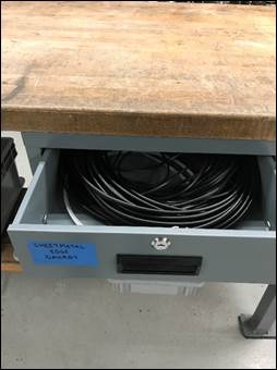
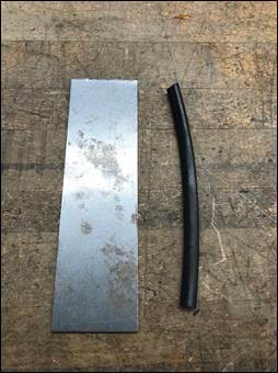
3.
Rubber
Edge Guard. This material is
located in the sheetmetal table drawer labeled Sheetmetal Edge Guard. Cut to required
length and slide over the edges of sharp sheetmetal parts. The
edge guard can be used on both straight and curved edges.
4.
Turret Punch Press. As explained on page 4
of the Sheetmetal
Design
Guide, the turret punch press punches various size holes
(3/16″ – 1-1/4″) in sheetmetal up to 16GA in thickness. All punching should
be done while the workpiece is in a flat (i.e. unbent or
welded) state. When
using the punch press you must activate the turret release
handle and rotate the turret to load the correct punch and die
set into the ram. After
punching each hole it is necessary to rotate the part around
the punch while sliding it downward to release it from the
punch.
5.
Cutting Tighter Radii, Channels, or Notches on
Do-All. Cutting tighter
radii, channels, or notches on the Do-All requires a technique
called relief cuts, where multiple auxiliary cuts are first
made perpendicular to the desired cut line to rough the part
out, and then the blade is used like a high speed file to cut
all the way to the target cut line. The technique shown
in the following video works equally well on wood or on metal.
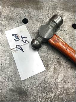
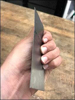
6.
Flattening
Improperly
Produced Bends. To correct (i.e.
flatten) an improperly produced sheetmetal bend, repeatedly
clamp the part in a sheetmetal vise or lay the part on the
welding table and strike it repeatedly with a hammer. Use eye and
ear protection and call out “EARS!” before
striking the part.
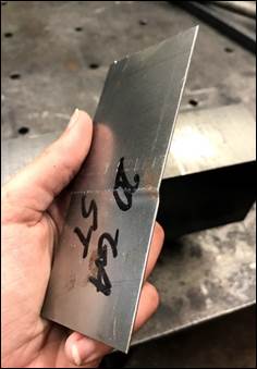
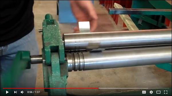
7.
Rolling
Sheetmetal. The lab has two
sheetmetal rolling machines: a small one and a larger one. Both machines work
the same way: there are two fixed rollers and a third moveable
roller whose centerline distance can be adjusted with respect
to the two fixed rollers.
A piece of sheetmetal is insert between the rollers and
rolled forward and backward to uniformly bend the material
into an arc. The
best way to learn how to use the roller is to just grab a
piece of metal out of the sheetmetal scrap bins and roll a
radius or a ring.
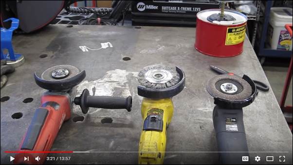
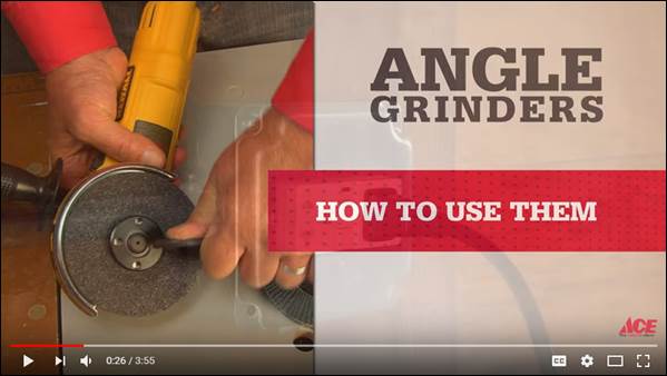
8.
Angle
Grinders. Angle grinders are
helpful tools for metalworking, but they can also be very
dangerous if used improperly.
The following videos highlight common uses and
important safety precautions that must always be followed when
using angle grinders. Like
most tools in the shop, the best way to become comfortable
with these tools is to use them under supervision of an older
TA who has been trained by our lab staff. Here is a list of
points when using angle grinders:
a.
Always
wear the proper PPE (eye protection, face shield, welding
jacket, gloves)
b.
always
use the factory guards whenever possible
c.
unplug
the grinder or remove the battery when changing wheels
d.
always
check that the wheel in installed properly before turning it
on, and be especially cautious when installing thin cutoff
wheels
e.
run
newly mounted wheels for a few seconds in a protected area
before use to make sure the wheel isn’t defective / damaged
f.
attach
the auxiliary handle (if it has one) and always keep BOTH
hands firmly on the grinder AT ALL TIMES
g.
always
turn the grinder on away from workpiece and use light pressure
when contacting the workpiece
h.
contact
the workpiece between the 12:00 and 3:00 position on the
grinding wheel
Metrology
[RETURN TO T.O.C.]
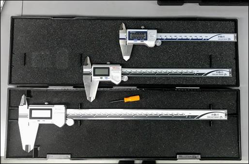
1.
Digital Calipers. Quality
6”, 8”, and 12” digital calipers are available in the
metrology cabinet. Digital
calipers are helpful when measuring larger parts or parts with
metric features due to the internal electronic conversion
between imperial and metric units. Additional benefits
of digital calipers are that they do not suffer from parallax
error and they have no components affected by chips. These particular Mitutoyo digital
calipers
have a resolution of 0.0005”, are IP67 rated for dust and 30
minute water immersion, and are therefore superior to analog
dial calipers in every way J. Following the metrology
rule of ten,
these quality digital calipers checked against a calibrated
standard can be trusted for tolerances within 0.005”.

2.
Outside Micrometers. Quality
micrometers are available in the metrology cabinet for
measuring parts features up to 8” in size. Most Mitutoyo micrometers have a resolution
of 0.0001”, which means when checked against a known standard
they can be trusted for tolerances within 0.001”.
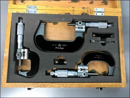
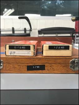
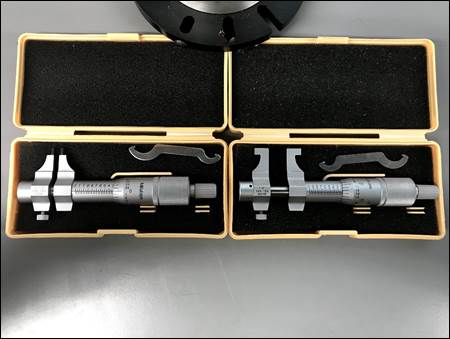
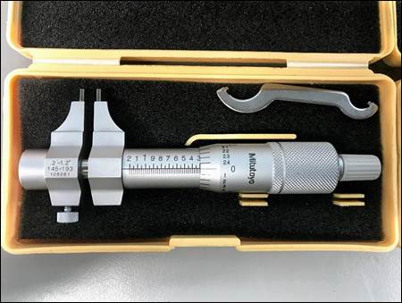
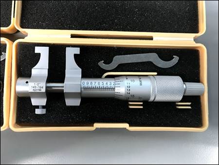
3.
Inside
Micrometers. Inside micrometers are used
to measure internal features, such as diameters or slots, but
only have a resolution of 0.001”. However, for
improved measurement precision they can be used in conjunction
with outside micrometers.
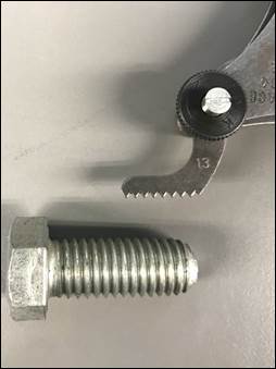
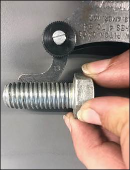
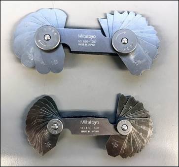
4.
Thread
Pitch Gages. Thread pitch gages allow
identification / verification of a fastener’s thread pitch,
and are available for both imperial and metric fastener
threads. In
conjunction with the fastener’s major diameter, the thread
pitch should allow absolute identification of a fastener’s
thread specification.
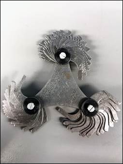
5.
Radius
Gages. Radius gages
allow identification / verification of a feature’s fillet
size, for both convex and concave radii.
6.
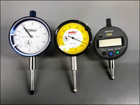
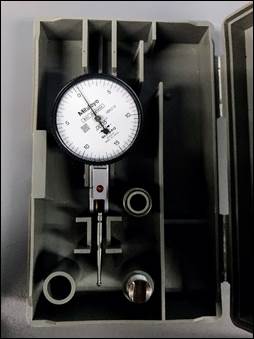
Indicators.
As
explained on the precision
metrology page,
indicators have many useful purposes in a design and
manufacturing environment, and we have a nice assortment of
all types.
7.
1-2-3
Blocks. These are so named due
to their dimensions: 1”x2”x3”.
Like parallels, these blocks are precision instruments
and so can be used to ensure a part or tool set-up is parallel
to a particular surface datum allowing for quick fixture and
tooling set ups. They
also have threaded and thru holes so that allow them to be
clamped to parts, fixtures, or machine tables.
Miscellaneous
[RETURN TO T.O.C.]
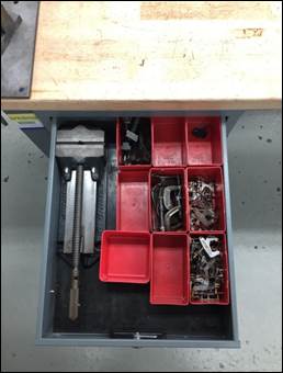
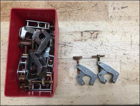
1.
Kant
Twist Clamps. These clamps are located on
one of the CNC carts by the VF-2, in one of the mill table
drawers, and under the welding table; they are used for
clamping parts together or to fixture plates. Advantages of these
clamps are that they are low profile, the floating jaws always
remain parallel to each other, they have built in v-blocks for
clamping round work, and they are copper-plated to resist
welding spatter. Notice
the aluminum fixture plate clamped in the vise in the second
photo; this provides a convenient method of alternative
workholding.

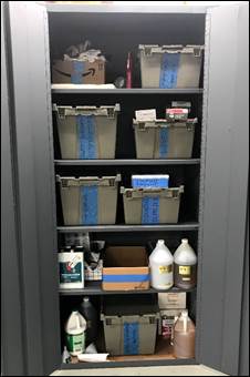
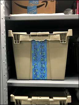
2.
Safety
Glasses. Spare student and TA safety
glasses are located in the second grey cabinet by the garage
door. If a pair
of safety glasses are scratched in the normal viewing area
they should be discarded and replaced. Extra glasses can
also be retrieved during high volume office hour sessions. Be respectful of the
number of safety glasses consumed during the semester and
always return them to the proper racks to minimize the risk of
scratching due to inconsiderate handling.
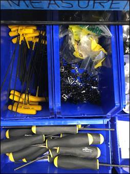
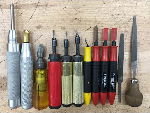
3.
Hand
Deburring Tools. Located in the black delrin
tool caddy on mill table.
Listed from left to right (1) Extended Countersink
Tool: useful for deburring the holes on the shoulder of the
wheel hub; (2) & (3) Countersink Tools: used on holes to
remove burrs along the cut edge for diameters of ½” or less;
(4-7) Whirly Bird Deburring Tools: utilize a swivel blade that
can deburr contours, straight edges and holes; (8-10)
Scrape-Burrs: have a spade like end best used on deburring
flat edges of parts; (11-12) Micro Files: a smaller version of
the larger files used in the lab for smaller parts or finer
material removal.
CNC Machines [RETURN TO T.O.C.]
1.
TM-2
Safety Caution. The TM-2 is an
open machine (compared to the VF-2 which has full enclosures
to allow the use of high pressure flood coolant), and as such,
does not protect the operator(s) from pinch points. Consequently, NEVER
prop your hand / arm on the tool changer carousel or your foot
on the base of the machine, as the risk for severe injury
during the briefest distraction is too great. Always respect the
machine and keep your body far enough away so you can safely
operate the machine.
[PHOTOs OF PINCH POINTS]
2.
CNC
Distraction Warning. Everything happens
A LOT faster on the CNC machines than on the manual
machines, so it is HUGELY important that you never run one
while distracted talking with someone. For
the same reason you must be EXTREMELY careful when teaching
someone else how to run one of these machines because of how
easy it is to be distracted focusing more on what you’re
saying to the person you’re teaching versus the actual
machine.
3.
TM-2
Work Offset. The TM-2 uses G57 work
offset for the lab hub threading demo. About once a year
this offset mysteriously vanishes for no apparent reason, so
ALWAYS run the demo with caution until you are sure the part
zeros are set properly (to the centerline of the rotary chuck
in X and Y and the top of the chuck jaws in the Z). When these zeros
need to be reset, there is a simple cylindrical part in the
mill table by the TM-2 for this purpose.
[PHOTO OF PROBING CYLINDER]
4.
CNC
Mill Coolant Nozzles. The coolant nozzles
on the CNC milling machines are usually adjusted so they are
pretty close to the rotating spindle / toolholder. It’s possible to
adjust them so close that they get pinched during a tool
change, so always leave 4 -6 inches of clearance.
[PHOTO OF COOLANT LINES]
5.
CNC
Mill Spindle Cleaning Plug. We have cleaning
plugs to prevent chips from entering the spindle during
cleanup. If you
use one of these, please do not leave it in the machine
spindle when done, as the next time the machine is started,
the spindle cleaning plug will get in the way of the first
tool change!